Valves classification
Without lengthy introductions, we note that the device can be of two types according to the principle of operation. It could be:
- dividing;
- mixing.
The features of each type of action are clear from their names. The mixing device consists of two outputs and an input. In other words, it is necessary to mix fluid flows, which may be required in order to reduce its temperature. By the way, this is the most optimal option for setting the desired mode in the “warm floor”.
The procedure for adjusting the temperature regime is extremely simple. You just need to know about the current temperature indicators of the incoming liquid flows, accurately calculate the required proportions of each of them so as to obtain the required indicators at the output. By the way, this device, subject to proper installation and adjustment, can also function for flow separation.
But the separating valve divides one flow in two, therefore, it is equipped with one inlet and two outlets. This device is used primarily to separate the flow of hot water in hot water systems. Although quite often it is found in the piping of air heaters.
Externally, both options are almost identical. But if you look at their cross-sectional drawing, their main difference is immediately visible. The rod, which is installed in a mixing-type device, has one ball valve. It is located in the center and blocks the main passage.
As for separating devices, the stem has two such valves, which are installed at the outlets. They function according to the following principle: one of them is pressed against the saddle, closing the passage, and the other, in parallel, opens passage No. 2.
According to the control method, modern models can be:
- electrical;
- manual.
In most cases, a manual device is used, which in appearance resembles an ordinary ball valve, but is equipped with three outlet pipes. But electric models with automatic control are used mainly in private homes, namely to distribute heat. For example, the user can set the temperature regime by room, and the working fluid will flow in accordance with the distance of the room from the heating device. As an option, you can combine it with a “warm floor”.
Video - Device in a boiler group
Three-way valves, as well as other devices, are determined in accordance with the pressure in the system and the diameter of the inlet. All this is regulated by GOST. And if the requirements of the latter are not met, this will be regarded as a gross violation, especially when it comes to the pressure indicator in the line.
Brass Fittings and HDPE Piping
We advise you to read our guide to the selection and installation of brass fittings for HDPE pipes, all
Why do you need a three way valve?
Such fittings are used to regulate water temperature in everyday life. The valve can:
- set the heating temperature of each radiator or part of the heating system. The thermal head is installed on one radiator or on several batteries installed in one room;
- lower and regulate the heating temperature of each water floor heating circuit. Very hot water (80-90°C) comes from the boiler, and up to 70-80°C from the buffer tank. The optimum temperature in floor heating pipes is +30°C, maximum – no more than 45°C. Therefore, when supplying hot water to the circuit, it must be diluted with cold water (from the return pipe). This is exactly what a three-way valve for a heated floor with a thermostat does;
- In modern hot water pipelines, a thermal valve can be installed in front of each water point (mixer or shower). By adjusting the valve accordingly, it is possible to obtain a precisely defined water temperature at the outlet;
- When starting solid fuel heating boilers, cold water must not be allowed to enter the heat exchanger. The heat exchanger is hot when fuel burns, and if cold water enters the heat exchanger, it may burst and the heating device will fail. Therefore, a three-way regulator is installed on the bypass between the return and water supply and adjusted in such a way that heated liquid always enters the heat exchanger. This ensures safe operation of the heating device.
Design and principle of operation of a three-way valve
The design of a three-way mixer includes the following elements:
- Sealed housing with three T-shaped pipes.
- Valve with internal T- or L-shaped channels. Most often, the bolt mechanism has the shape of a ball, less often a cone or cylinder.
- Stuffing box.
- A rod that transmits movement to the bolt mechanism.
- Control unit - handle (butterfly or lever) or drive.
The operating principle of a three-way valve is based on the rotation of the valve inside the body. An L- or T-shaped stroke drilled into the valve serves to pass flows. By turning, the shutter either opens all the holes in the pipes or closes one of them.
Let's consider the principle of its operation using the example of a heating circuit. A three-way valve is installed in the circuit so that one of its pipes is connected to the pipeline coming from the boiler.
The pipe located in the middle is connected through a bypass connection to the “return”, where the coolant has a lower temperature. The third pipe connects to the pipeline going to the radiators.
The shutter position is set by turning the handle:
- In the first position, transported flows are mixed, simultaneously coming from the circuit supplied from the heat generator and from the “return” circuit.
- In the second position, only hot coolant from the boiler is supplied to the heating circuit.
- In the third position, the flow of hot coolant is blocked, only cooled water from the return circuit is supplied to the system.
The nuances of installing a three-way valve in a heating system with your own hands
To ensure proper installation of all elements of the heating system, you should familiarize yourself with the possible nuances. Only in this case can the uninterrupted functioning of the circuit be guaranteed. For each such product, the manufacturer includes instructions that detail all the basic requirements.
To ensure that the installation of a three-way valve in a heating system is carried out correctly, you should ensure that the valve is in the correct position by paying attention to the tips that are on each body. They indicate the direction of water flow. These designations can be deciphered as follows:
- A – straight forward.
- B – bypass or perpendicular direction.
- AB – combined output or input.
In this case, you should take into account which valve model is to be installed. They can be with:
- T-shaped or symmetrical pattern;
- L-shaped or asymmetrical pattern.
In the first case, the installation is carried out in such a way that the thermal fluid can enter the valve through the end holes and exit through the central one. In the second, the inputs are one end and the bottom, and the output is the second end.
Another nuance that should be taken into account during the installation process: the spatial position of the thermostatic head or drive. They should not be pointing downwards.
Attention! Before starting work, be sure to turn off the water and make sure that there are no coolant residues inside the pipeline.
The valve should be located in a place where it can be easily accessed. The location of the fittings must allow all necessary manipulations to be performed.
Thus, a three-way valve can be safely called an essential element of the heating system. If you use a thermo-mixing valve for heated floors, share in the comments which manufacturer you prefer and why. It will also be interesting to know the features of its installation.
Design and principle of operation
To understand what the thermo-mixing three-way valve of the most common saddle type consists of and how it works, you should study the diagram below. Inside the brass body with three nozzles, 3 chambers are arranged using the casting method, the passages between which are blocked by poppet valves. They are fixed on one axis - a rod coming out of the body on the fourth side.
In a 3-way mixing tap, the outlet pipe (from where the mixed water comes) is always open, the remaining 2 fittings are alternately closed with a thermal head
The operating principle is as follows: when you press the rod, the passage for one flow will begin to open and gradually close for another, resulting in water of the required temperature in the mixing chamber of the valve. It leaves the brass body of the element through the third pipe. The force of pressing on the rod is adjusted by a thermal head with an external temperature sensor installed in accordance with.
The whole process is worth explaining in more detail:
- Imagine that an insufficiently heated coolant comes from the hot water side. Then the mechanism passes it further, and the third pipe is closed. The remote sensor is filled with a heat-sensitive liquid and is connected through a capillary tube to a reservoir (bellows) inside the thermal head.
- When the sensor heats up, this liquid expands, its volume in the tube and bellows increases, as a result of which the latter begins to press on the three-way valve rod. The moment of pressing is determined by the adjustment on the scale of the thermostatic head, set to the required temperature.
- After this, cold water from the third pipe is mixed into the flow of heated water and the temperature of the water at the outlet of the thermal valve remains unchanged, although heating of the coolant at the inlet continues.
- If the incoming water continues to heat up above normal, then to maintain the set outlet temperature, the thermostatic valve can completely close the inlet and open the side flow. In this case, the rod lowers to its lowest position.
- As soon as the sensor detects cooling of the coolant, the head slightly releases the stem, the valve seat on the hot side opens and the addition of heated water begins.
If we are talking about a dividing valve, the principle of its operation is almost the same, only when you press the rod, one flow begins to divide into two. But in the switching element, the direction of movement is changed by the electric drive, which is described in detail in the video:
Watch this video on YouTube
Design and functionality of the device
Three-way valves (TC) differ in size and material: stainless steel and bronze. The body can be made of either metal or polymer material. Although the latter is not very popular.
Valve types
The design has 3 openings: an inlet and two outlets; inside there is a drive that controls the flows to obtain a given temperature.
Structurally, the product is designed to interrelate the action of a pair of two-way valves. The main difference is that TC does not stop the flow of the medium, but regulates its intensity. 3-way devices are divided into groups according to the adjustment system: “rod-seat” and “ball-socket”, and can be paired with a Hertz thermal head.
Control of the movement of the rod is usually carried out by an electromechanical type drive, and is used for installation in automatic control systems for thermal processes of the Proterm boiler and other modern solid fuel engines.
Valve design
The principle of operation of the heating system is based on mixing 2 temperature flows of the coolant on the supply and return, into a common flow, with a temperature indicator set by the user.
The medium in the internal cavity of the device moves from one pipe to another until its temperature changes to the desired size.
Rules for installing a three-way valve
- The installation site must be freely accessible.
- The “tee” is installed with the lever up or sideways (outward). The control lever should move freely in the desired direction.
- Markings in the form of arrows on the device body will tell you how to correctly connect it to the system. The arrows indicate in which direction the flow will move.
- If the quality of the coolant is low, it is advisable to install a filter in front of the three-way mixer.
- In the heating circuit, a “tee” is installed in front of the circulation pump.
- The threaded connection must be sealed with flax fiber and treated with a sealant.
- When connecting for welding, it is necessary to avoid the formation of scale inside the line.
Rules for operating a three-way valve
The “tee” installed in the system requires periodic inspection for wear and leaks. If a leak is detected, you can try tightening the threaded connection. If the leak cannot be eliminated, the mixer will have to be disassembled. Very often it is the O-rings that wear out. Replacing them and cleaning the elements from scale extends the life of the device.
To reduce the wear of the device, it must be periodically lubricated with a special plumbing product.
Common mistakes and problems when installing a three-way valve
Errors made when installing a “tee” not only shorten its service life, but also negatively affect the operation of the entire pipeline:
- Incorrect connection of pipes increases hydraulic resistance.
- The use of models with fluoroplastic seals in systems with operating temperatures above 150 °C will require replacing the three-way mixer after 2-3 months.
- Installation in a hard-to-reach location will complicate preventive maintenance procedures.
Expert advice
- During installation, the brass body is easily damaged. To prevent this, it is better to place a thick fabric gasket under the wrench.
- To install a three-way valve on plastic pipes, special adapters are needed.
- Instead of a “tee”, you can use 2 conventional two-way valves. They must work according to a reverse pattern: when one opens, the other closes.
Functional fundamentals and basic types of collectors
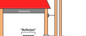
The operating diagram of a heated floor collector is quite simple. The coolant from the heating boiler enters the supply distributor. It is recommended to place it at the top (above the return comb), however, depending on local installation features, as well as the type of connected mixing unit, it can also be installed at the bottom. The collector body has two or more branches equipped with appropriate shut-off and control valves. Along each of the branches, the coolant is redirected to certain pipelines of the transformer substations. The output end of the pipe loop is closed on the return comb, which directs the collected total flow to the heating boiler.
Obviously, in the simplest case, a manifold for a water heated floor is a piece of pipe with a certain number of threaded elbows. However, depending on what final configuration it receives, the complexity of its assembly, settings and cost can vary significantly. Let's first consider the most popular basic models of distributors for water TP.
With fittings for connecting circuits
One of the most budget-friendly, but completely ready-to-use, is a comb with inlet/outlet threads and fittings for connecting metal-plastic or cross-linked polyethylene pipes. One of these models is shown in the photo below.
Figure 2.
With integrated taps
In the minimum configuration you can also find a manifold for underfloor heating equipped with two-way ball valves (Fig. 3). Such devices do not provide for contour adjustment - they are only designed to turn on or off individual heating branches. Considering that a heated floor system is purchased and installed to increase the comfort of residents, which is ensured by precise adjustment of the system, the advisability of using such combs is purely selective. The photo shows a similar three-circuit manifold with integrated two-way ball valves.
When purchasing these budget options for distributors, it should be taken into account that their use requires fundamental knowledge, as well as extensive experience in installing heating systems. In addition, purchasing savings are quite conditional, since all additional equipment will have to be purchased separately. Almost simplified manifolds for warm water floors without modification are suitable only for auxiliary systems with one or two loops of short length. They are also suitable for several circuits, but having identical thermal and hydraulic characteristics. After all, the design of such combs does not provide the technical possibility of installing control and regulatory equipment directly on each branch.
Figure 3.
With control valves
The next level, both in cost and functionality, is a distribution manifold for underfloor heating with control valves. Such devices, when operated in manual mode, can already provide adjustment of the intensity of coolant supply to individual heating circuits. For them, in most cases, it is technically possible to install actuators with servo drives instead of manual valves. The drives can be connected either directly to electronic temperature sensors installed in the premises, or to a central programmable control device. Figure 4 shows an example of a comb with control valves.
Figure 4.
Assembly of supply and return manifolds
The economical version of the manifold for a warm water floor also includes paired assemblies of supply and return distributors (Fig. 5). They may already have additional mounting holes or installed Mayevsky taps, safety groups, quick-release threaded “Americans” for easy connection to the primary heating circuits or mixing unit.
Figure 5.
Purpose and design of a three-way valve
This device serves to mix and separate coolant flows circulating in one closed system. Separation or mixing of water flow is necessary if there are several circuits in a house or apartment that must operate in a strictly defined temperature range.
A classic example of such a system is the heating of a house or apartment, in which the main air heating is carried out by external radiators, and additional heating is performed by a so-called system. “warm floor”. If your home has rooms of different sizes, then it is logical that different amounts of coolant are needed to uniformly heat the air in the rooms. A larger room may have two or more radiators or one larger one, while the rest may have standard radiators.
The three-way valve serves to distribute the coolant while regulating its temperature. To do this, the valve device provides three outlets, due to which the mechanism looks like a regular tee. The function of a three-way valve, depending on the purpose and device, is limited to three tasks:
- mixing several streams of hot water into one;
- separation of one common coolant flow through several circuits;
- switching the flow of the working environment in certain directions.
We recommend that you read: Replacing old pipes with polypropylene on your own
Attention! The use of a three-way valve makes it possible to simplify the control of a heating function consisting of several circuits; the use of the device replaces a large number of shut-off and control valves - switches, valves, gate valves.
The three-way valve device is an all-metal body made of stainless steel, brass or cast iron, protected by galvanization. The body shape is T-shaped, consisting of two side and one lower pipe. Inside the device there is a mixing chamber and a thermal head, which performs the function of controlling the temperature of the coolant.
A rod having one or two flat or spherical (ball) valves is attached to the thermal head inside the valve. Moving the valve inside the valve opens the top passage to start hot water and closes the other two passages.
The valve is connected to the heating system in such a way that the coolant passes through the device from the supply and discharge circuits. Temperature regulation is carried out by mixing the cooled coolant from the so-called. heating system return with heated water from the boiler or boiler. Dosing of cooled water occurs automatically due to the operation of temperature sensors and an electric drive.
At a given temperature range, part of the valve that directs the flow of water into one circuit remains open so that cooled water flows freely into the underfloor heating system. As soon as the coolant reaches the desired temperature, to prevent further cooling, the valve shuts off the flow of cold water and opens the pipe with hot water from the supply circuit.
Do-it-yourself valve installation
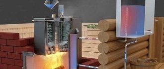
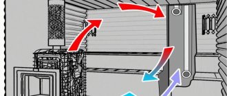
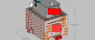
When installing a three-way thermomixing valve with your own hands, you need to take into account the layout of your boiler and heat supply in the house. Strictly follow all instructions and connection points. Also carefully read the diagram of the main components. The units include all the units that are installed near our boiler to supply the home.
- We install the pump on the return line
. If it stands on the feed from the boiler, it will quickly deteriorate. - A connection is required, which can also be done with your own hands; it will protect the entire water connection unit from overheating.
- In a natural coolant circulation system, the cold water supply pipe is connected to the boiler inlet pipe (usually at the bottom). Hot water pipe – to the boiler from above (as shown in the diagram). It should be taken into account that the hot coolant pipe must be made of good steel, copper, cast iron or bisalloy
, since the water temperature can heat up to 100-105 degrees Celsius. - Connecting the expansion tank (either at the return or at the outlet - it doesn’t matter, see the diagram) serves as a kind of fuse and buffer in our unit.
- Connection to the safety safety group: to a pressure gauge indicating the pressure in the boiler; to the emergency pressure relief valve; automatic safety air vent. These safety devices are installed at the boiler outlet to control the heated coolant (see diagram).
- Installation and connection according to the heat accumulator diagram.
- After this, connect the three-way mixing valve strictly in accordance with the diagram
; it is this valve that will mix the hot water from the heat accumulator with the cold water from the return.
If you have reached this article through a search, then you have probably already heard something about mixing pipeline fittings used in heating systems of private houses and apartments. So, without much preamble, we suggest discussing 3 questions: how a thermostatic three-way valve works, where it should be installed and how to choose the right one so as not to spend extra money.
The task of any 3-way valve is to supply water of the required temperature into the main line by mixing or separating 2 streams. Accordingly, the element is equipped with three outputs, one of which is always open, and the other two are completely or partially blocked during operation. Hence the name of the valve – three-way (sometimes they also say “three-way”, which is not correct).
According to the method of preparing the coolant at the required temperature, thermostatic valves are divided into 2 groups, shown in the photo:
- Mixing. They are supplied with 2 streams of water – hot and cooled (the inlets are designated by the letters “A” and “B”), and from the third pipe (marked “AB”) a mixture of the set temperature flows. On the brass body there is a mark in the form of an arrow converging in two directions.
- Separation or distribution. The incoming coolant is divided into 2 flows of controlled quantities. Marking on the body - 2 diverging arrows or the letters “A”, “B” on the outlet pipes and “AB” on the inlet.
According to the principle of operation, three-way valves are also divided into two types - seat and ball. The device of the former is similar to ordinary water valves, only instead of a threaded rod, a push rod is used. A plate is attached to it, moving between two saddles and blocking 2 passages in turn. Pressing the rod is carried out in three ways:
- built-in thermocouple
- thermal head with remote temperature sensor
- servo drive.
Ball thermomixing valves operate on the same principle as valves, only with three outlets. They are controlled manually or from an electric drive that rotates the rod at the command of the automation. The elements are full bore and have high throughput, which means lower hydraulic resistance. The disadvantage is the dependence on the mains voltage and the need to install an uninterruptible power supply (UPS).
Types of three-way valves and their features
There is a generally accepted classification of three-way valves, according to which they are divided into separating and mixing. Externally, both types of devices are identical, but inside they have significant differences:
- Mixing devices have one spherical valve inside, located in the center of the chamber. It blocks the flow of the working medium from the supply passage.
- Dividing valves have two valves inside connected to a stem. When adjusting the position of the rod, one of the valves is pressed against the seat and blocks the flow of the working medium into one circuit, opening in parallel the flow of hot water into the other circuit.
We recommend that you read: How and with what to make a hole in a pipe made of different materials
According to the control method, three-way valves are divided into devices with manual and mechanical drive:
- Manual valves have a fairly simple design, reminiscent of a conventional ball valve. A manual shut-off device can be installed where there is no need to strictly regulate the temperature of the working environment, for example, when distributing coolant between heating radiators of different capacities.
- The electrically driven device operates with the participation of a thermostat equipped with a sensitive temperature sensor, which provides it with almost complete autonomy. For its operation, it is enough to set the temperature range, and the valve itself will dose cooled and hot water to maintain the desired hydraulic regime.
Note! Automatic valves with an electric drive are usually installed in systems where a “warm floor” is connected to the boiler along with a conventional heating system.