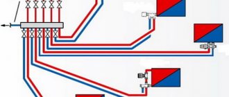
In any heating system consisting of several radiator batteries, their heating temperature depends on the distance to the heating boiler - the closer to it, the higher the degree. Therefore, for its efficient operation and to meet various requirements for heating the premises, a balancing valve for the heating system is built into the main line.
The construction market offers a wide range of these control valves, which have the same principle of operation and some differences in design. It is useful for any master or owner who independently carries out heating in his private home to know why a balancing valve is needed, the rules for its installation and settings to ensure the efficiency, economy and functionality of the heating main.
Rice. 1 Thermal imaging of a residential building with unbalanced heating
What is a balancing valve
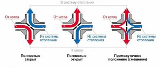
To maintain the same temperature in the batteries, they are adjusted by changing the water flow - the less coolant passes through the radiator, the lower its temperature. You can shut off the flow with any ball valve, but in this case it will not be possible to set and adjust the same temperature in the devices if there is more than one heating device. It will have to be measured with temperature sensors on the surface of the batteries and by rotating the valve to experimentally set its desired position.
Balancing valves, which are widely used for adjustment, effectively solve the problem of maintaining balance automatically or through simple calculations of the required flow rate and the corresponding settings in the devices. Structurally, the device partially blocks the flow of the coolant, reducing the cross-section of the pipes, similar to any shut-off valve, with the difference that the required supply volume is accurately set on the adjustment scales using the rotary handle of the mechanism or automatically.
Why use it
Installing balancing valves in the heating system, in addition to maintaining the same temperature of the radiators, in an individual home brings the following effect:
- Precise adjustment of the coolant temperature allows you to set its value depending on the purpose of the premises - in living rooms it can be higher, in utility rooms, storerooms, workshops, gyms, and food storage areas, you can set it lower using balancers. This factor increases the comfort of living in the house.
- Changing the coolant flow using a balance valve regulator depending on the purpose of the premises brings a significant economic effect, allowing you to save on fuel.
- In winter, when the owners are absent, constant heating of the home is necessary - with the help of balancing valves, you can adjust the heating system with minimal fuel consumption and maintain a constant temperature in all rooms. This advantage also saves financial resources for the owners.
Rice. 3 Manual balancing valves for heating and hot water supply (DHW) systems in the house
Valve types
Heat supply systems can have a permanent or variable consumption of a thermal energy source. Depending on this indicator, there are two types of valve:
- manual;
- auto.
Manual balancing valves are usually used with a constant flow rate of a thermal energy source. The adjustment is carried out by means of a working cone, the extension of which is regulated by mechanical rotation of the handle. In turn, manual valves are divided into the following types:
- single-pipe;
- two-pipe.
Manual balancing valve
Automatic balancing valves are used for hydraulic balancing of heating systems and other systems with variable coolant flow. An example of using an automatic valve would be a two-pipe system with a thermostat (a typical version of a variable flow system). For hydraulic balancing, an automatic balancing valve is used in conjunction with a shut-off and balancing valve.
Automatic balancing valve
When thermostatic valves, due to changes in air temperature in the room, change the flow of coolant through the heating devices, and therefore the pressure drop, it is necessary to ensure that the difference does not exceed the set value. An automatic valve solves this problem.
When the thermostat closes, the differential increases to the value set on the valve. As a result, the valve also closes, creates optimal conditions for the operation of thermostatic valves and protects against too large differentials, therefore preventing noise.
Each such regulator is equipped with a control block designed specifically for a specific type and size of valve, which ensures accurate pressure differential maintenance. At the same time, the coolant is consumed efficiently without overspending, and the heating system is hydraulically stable, which eliminates the need for constant adjustment and reconfiguration of the system by operational services.
Design and operating principle
The principle of operation of balancing valves is to block the flow of liquid with a retractable valve or rod, causing a reduction in the cross-section of the passage channel. The devices have different designs and connection technologies; in a heating system they can additionally:
- Maintain the pressure drop at the same level.
- Limit coolant consumption.
- Shut off the pipeline.
- Perform drain functions for working fluid.
Structurally, balancing valves resemble conventional valves; their main elements are:
- Brass body with two through pipes with internal or external threads designed to connect to a line with standard pipe diameters. The connection in the pipeline, in the absence of a threaded fitting with a movable threaded nut (American), is made through its analogues - additional adapter couplings with different union nuts.
- A locking mechanism, the movement of which regulates the degree of blocking of the coolant passage channel.
Rice. 4 Danfoss LENO MSV-B manual balancing valve
- Adjustment handle with scale and setting indicators, allowing you to adjust the flow inside the device.
- Modern models are equipped with additional elements in the form of two measuring fittings, with the help of which the flow volumes (throughput) are measured at the inlet and outlet of the device.
- Some models are equipped with a shut-off ball mechanism that allows you to completely shut off the flow, or have the function of draining liquid from the water supply.
- High-tech modern types can be controlled automatically; for this, instead of a rotating head, a servo drive is installed, which, when power is supplied, pushes the locking mechanism, and the degree of channel closure depends on the amount of voltage applied.
Rice. 5 Danfos AB-QM automatic balancers - design
Operating principle
Balancing valves are designed to use them to achieve maximum efficiency of all heating elements of the system, as well as to adjust it at any time.
We recommend that you read: The use of shut-off valves to shut off the flow in water pipelines
The principle of operation of the device is that the valve changes the flow area through the operation of parts.
When the handle designed for adjustment is rotated in either direction, torque is transmitted to the nut and spindle. Unscrewing causes the last element to rise from the lower position to the upper one. Being at the bottom, it tightly blocks the flow, preventing coolant from passing through the pipes.
Thus, when the valve is unscrewed, the spool allows a certain amount of energy to pass through, increasing the passage; when it is tightened, the passage narrows, which reduces or completely blocks the flow. Rotating the spindle changes the throughput of the device.
Any adjustment of the flow area entails a change in the valve’s resistance to the flow of water or any other coolant.
Water, just like any other energy carrier, always follows the path of least resistance. As a result, distant heating circuits do not heat up enough. The balancing valve creates artificial resistance in the path of water, accelerating its flow to distant circuits. Thus, the device provides the calculated pressure drop.
With such work, the main task of the entire structure is to ensure maximum tightness. To do this, manufacturers use several options for sealing rings:
- from fluoroplastic;
- made of thick rubber;
- made of metal.
For precise tuning, you need to study the technical specifications, which describe the operation of the system at certain shutter positions.
Types of balancing valves
Balancing in heating systems is carried out using two types of control valves:
- Manual . The design is a body made of non-ferrous metals (bronze, brass), which houses a balancing element, the degree of extension of which is set by turning a mechanical handle.
- Automatic . Automatic devices are installed on the return pipeline together with partner valves that can limit the flow of the medium by presetting the throughput. When connected, they are connected to partners via an impulse tube connected to the built-in measuring nipple. If the fitting is installed to supply water in a direct line, its handle is red; when installed in a return line, it is blue (Danfoss models). Automatic types include models controlled by a servo drive, which is supplied with constant voltage.
Balancing valve for heating system
Existing heat supply systems are conventionally divided into two types:
- Dynamic. They have conditionally constant or variable hydraulic characteristics, these include heating lines with two-way control valves. These systems are equipped with automatic balancing differential regulators.
- Static. They have constant hydraulic parameters, include lines with or without three-way adjustment valves, the system is equipped with static manual balancing valves.
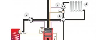
Rice. 7 Balancing valve in the line - installation diagram of automatic fittings
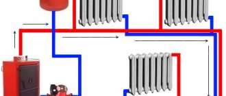
In a private house
In a private house, a balance valve is installed on each radiator; the outlet pipes of each of them must have union nuts or another type of threaded connection. The use of automatic systems does not require adjustment - when using a two-valve design, the supply of coolant to radiators installed at a large distance from the boiler is automatically increased.
This occurs due to the transfer of water to the actuators through a pulse tube under lower pressure than that of the first batteries from the boiler. The use of another type of combined valves also does not require calculating heat transfer using special tables and measurements; the devices have built-in control elements, the movement of which occurs using an electric drive.
If a manual balancer is used, it must be adjusted using measuring equipment.
Rice. 8 Automatic balancing valve in the heating system - connection diagram
To determine the volume of water supplied to each radiator and, accordingly, balancing, an electronic contact thermometer is used, with which the temperature of all heating radiators is measured. The average supply volume per heater is determined by dividing the total value by the number of heating elements. The greatest flow of hot water should flow to the furthest radiator, a smaller amount to the element closest to the boiler. When carrying out adjustment work using a manual mechanical device, proceed as follows:
- Open all control valves all the way and turn on the water; the maximum surface temperature of the radiators is 70 - 80 degrees.
- Using a contact thermometer, measure the temperature of all batteries and record the readings.
- Since the furthest elements must be supplied with the maximum amount of coolant, they are not subject to further regulation. Each valve has a different number of revolutions and its own individual settings, so the easiest way is to calculate the required number of revolutions using the simplest school rules based on the linear dependence of the radiator temperature on the volume of passing coolant.
Rice. 9 Balancing fittings - installation examples
- For example, if the operating temperature of the first radiator from the boiler is +80 C., and the last +70 C. with the same supply volumes of 0.5 m3/h, on the first heater this indicator is reduced by a ratio of 80 to 70, consumption will go less, and the resulting volume will be 0.435 m3/h. If all the valves are not set to the maximum flow, but set to the average value, then you can take the heaters located in the middle of the line as a guide and similarly reduce the throughput closer to the boiler and increase it at the farthest points.
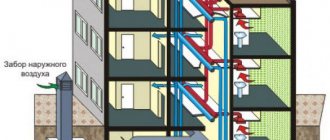
In a multi-storey building or building
The installation of valves in a multi-storey building is carried out in the return line of each riser; if the electric pump is far away, the pressure in each of them should be approximately the same - in this case, the flow rate for each riser is considered equal.
To set up in an apartment building with a large number of risers, it uses data on the volume of water supplied by an electric pump, which is divided by the number of risers. The resulting value in cubic meters per hour (for the Danfoss LENO MSV-B valve) is set on the digital scale of the device by rotating the handle.
How to adjust radiator network balance
Each valve comes with instructions upon purchase, which contain information on how to calculate the number of turns of the handle.
Using the attached diagram, you can permanently regulate energy consumption, saving on heating.
According to the instructions, you need to turn the valve to a certain level.
There are two ways to adjust the valve.
Method 1
Experienced specialists have a simple and proven way to adjust the system.
They divide the valve speed by the number of radiators located around the entire perimeter of the room. It is this method that allows them to accurately determine the flow adjustment step. The principle is to close all taps in the reverse order - from the last to the first radiator.
For a more clear example, let's take the following system characteristics.
The dead-end system has 5 batteries, which are equipped with manual valves. The spindle in them is adjustable by 4.5 turns. It is necessary to divide 4.5 by 5 (the number of radiators). The result is a step of 0.9 turns.
We recommend that you familiarize yourself with: PPM (polymer-mineral foam) insulation for pipelines
This means that the following valves must open the following number of turns:
| First balancing valve | by 0.9 revolutions. |
| Second balancing valve | 1.8 revolutions. |
| Third balancing valve | 2.7 revolutions. |
| Fourth | 3.6 revolutions. |
Method 2
There is another, very effective way of adjustment. It is carried out faster, and includes the ability to take into account the individual features of each radiator. But to carry out such an adjustment, you will need a special contact-type thermometer.
The whole process proceeds in the following sequence:
- Open all valves without exception and allow the system to reach an operating temperature of 80 degrees.
- Measure the temperature of all batteries using a thermometer.
- Eliminate the difference by closing the first and middle taps. The latter mechanisms do not need to be adjusted. As a rule, the first valve turns a maximum of 1.5 turns, and the middle ones - 2.5.
- Do not make any adjustments for 20 minutes. After adapting the system, take measurements again.
The main task of this method, like the previous one, is to eliminate the difference in temperature at which all batteries in the room heat up.
Valve installation
When installing the valve, it is necessary to place it in the direction of the arrow on the body, which indicates the direction of fluid movement, to combat turbulence, which affects the accuracy of the settings. Select straight sections of pipeline with a length of 5 diameters of the device and its location points and two diameters after the valve. The equipment is installed in the return branch of the system; a plumbing adjustable wrench is sufficient to carry out the work; installation is carried out in the following sequence:
- Before installation, be sure to flush and clean the pipeline system to get rid of possible metal shavings and other foreign objects.
- Many devices have a removable head; for ease of installation in pipes, it should be removed in accordance with the instructions.
- For installation, you can use flax fiber with appropriate lubricant, which is wound around the end of the pipe and the battery outlet fitting.
- The control valve is screwed onto the pipe at one end, the other is attached to the radiator with special washers (American adapter coupling), which is placed on the outlet radiator fitting or screwed into the valve, playing the role of a connecting coupling.
Setting the balance valves
To balance the heating in a private house, select manual devices of the required diameter, selecting and configuring them using the appropriate diagram included in the passport. The initial data for working with the graph are the supply volume, expressed in cubic meters per hour or liters per second, and the pressure drop, measured in bars, atmospheres or Pascals.
For example, when determining the position of the adjustment indicator of the MSV-F2 modification with a nominal bore DN equal to 65 mm. at a flow rate of 16 cubic meters per hour. and pressure drops of 5 kPa. (Fig. 11) on the graph, connect the points on the corresponding flow and pressure scales and extend the line until the conventional scale intersects the coefficient Ku.
From the point on the Ku scale, draw a horizontal line for diameter D equal to 65 mm, find the setting with the number 7, which is set on the handle scale.
Also, for the selected diameter of the device, its adjustment is carried out using the table (Fig. 12), from which the number of spindle revolutions corresponding to a certain flow is determined.
Rice. 11 Determination of the position of the valve scale at a known pressure and a certain water supply
Rice. 12 Example table for manual configuration
Balancing valve: how it is used, why and when it is installed in a home heating system
In most modern heating systems of private houses, balancing valves are installed. Their use is forced, and is not a sign of a high-quality system, but rather the opposite - we needed to balance something there because of the difficulties. Now we do not have the simplicity that we previously had in a gravity-fed system with huge diameters and cast-iron radiators. Now we fine-tune our heating systems with balancing valves. Let's take a closer look at their design and application, since without them the heating system in a private home may not be operational.
Why do some radiators heat up while others don’t – where is the balancing?
The hydraulic resistance of individual branches in the heating system can differ so significantly that the radiators will have noticeably different temperatures. This means that too different amounts of coolant, and therefore energy, move through them.
When one room is warm, another is cold, or one wing of the house is warmer than the other, this is not at all acceptable for residents. To correct the situation, balancing valves will be required. With their help, you can balance the heating system in the house, namely, change, increase or decrease the hydraulic resistance of a branch and thus create approximately the same fluid flow through heating devices or fulfill other project requirements.
In the case of a complex heating scheme, the radiators in the house will heat up evenly if the system is properly balanced. For the simplest and most economical heating systems, balancing valves are not installed.
Design and operating principle of balancing valves
The design of the balancing valve resembles a valve. Rotating the adjusting knob changes the position of the poppet valve, the degree of opening of the bypass hole, and therefore the hydraulic resistance (the amount of coolant passing) in this branch.
Balancing valves are divided into:
- Manual adjustment - the valve is adjusted manually, which sets a certain operating mode of the system, which does not change until the next human intervention.
- Automatic adjustment - adjustment is carried out automatically, often by a servo drive according to the electronics, depending on pressure drops at some points in the system or on the valve itself. This allows you to constantly adapt to changes in the system, maintaining the same fluid flow through the valve or set pressures at some point….
Which balancing valves should be used: manual or automatic?
In conventional heating systems of private houses, as a rule, manual balancing is used - preliminary adjustment of the system. Automatic adjustment of modes is often not required.
But in complex circuits in large private houses, in apartment buildings, it may be advisable to use automatic balancing valves controlled by servo drives or mechanical pressure regulators. In such circuits, significant changes occur over time, turning on and off individual branches (energy consumers) with significant pressure fluctuations at different points. Which leads to changes in the operation of other parts of the system. To maintain the initially set operating mode (initial balancing), automatic control of the balancing valves is installed.
A mechanically controlled circuit for the pressure regulator has become more widespread. Setting information is obtained from the balancing valve with a pressure vent.
Where are balancing valves used in a private home?
Any installer who respects his wallet will recommend equipping every radiator in the house with a balancing valve on the return line, instead of a shut-off valve. This does not always make any practical sense, but it does raise the price of equipment and, conditionally, installation work.
- In practice, balancing between radiators may be necessary if the number of radiators in one dead-end branch is 5 pcs. and more.
- Balancing between branches is almost always provided in a radial connection diagram, since the resistance of individual branches can vary significantly. In this case, balancing valves are installed on the distribution manifold.
- The same is true with the underfloor heating system - each circuit is supplied with a manual balancing valve on the collector return.
- Balancing valves controlled by servo drives can be installed at the collector supply - a common solution in modern automated systems.
- Manual balancing valves may be needed between individual heating branches of a house connected to the same pipeline. For example, a Tichelman loop with 10 radiators on the 1st floor will need to be balanced with 2 radiators in a dead end in the attic, which are connected to it in parallel, etc. Therefore, balancing valves are installed in the return of clearly “unequal” branches.
The expert recommends that there is no need to load the system with balancing resistances. It is necessary to strive to reduce resistance and thereby ensure stable operating conditions for the equipment and economical operation of the pump.