Setup and adjustment
So, let's look at the Baksi gas boiler - operating instructions, setup and adjustment. To set up the boiler, just set the desired temperature on the room thermostat - the unit will do the rest itself. All data is shown on the display. The most convenient are thermostats with a programming function, through which you can plan the boiler operating schedule for a day or a week in advance (depending on the model).
In Luna-3 Comfort series boilers, the controller is removable and can control the operation of the boiler remotely. It looks like a panel with a display and keys, which also contains a room temperature sensor.
Wall-mounted boiler BAXI Luna 3
The controller is placed in one of the rooms at any convenient place and with its help the operation of the heater is adjusted. On it you can view the results of self-diagnosis and, if necessary, view a list of recent errors - it is stored in memory.
Baxi Luna HT 1.450, 1.550, 1.660.
Setting the gas valve.To adjust the gas valve, perform the following operations sequentially: 1) adjusting the maximum power. Check that the CO2 content measured in the flue pipe when the boiler is operating at maximum power corresponds to that given in Table 1. Otherwise, turn the adjusting screw (V) located on the gas valve clockwise to decrease the CO2 content and counterclockwise to increase it. 2) minimum power adjustment. Check that the CO2 content measured in the flue pipe when the boiler is operating at minimum power corresponds to that given in Table 1. Otherwise, turn the adjusting screw (K) located on the gas valve clockwise to increase the CO2 content and counterclockwise to decrease it.
Pi gas pressure measurement point at supply
Pout gas pressure measuring point at the burner
P pressure measuring point to measure the deviation Pl signal input from the fan.
V gas pressure adjusting screw K deviation adjusting screw.
To make setting the gas valve easier, you can set the “setting function” on the boiler control panel. To do this you need:
1) press the buttons (2-3) simultaneously until the “sign” appears on the display along with the symbol (approximately 6 seconds);
2) use the buttons to adjust the fan speed at maximum and minimum power (%PWM);
Note To quickly set the minimum and maximum power, press the buttons respectively;
3) press one of the two buttons to finish programming
Tab.1
| G20 – 2H – 20 mbar (natural gas, nominal pressure - 20 mbar) | G31 – 3P-37 mbar (propane, nominal pressure – 37 mbar) | |
| CO2 content at maximum thermal power consumption | 8,7 % | 10 % |
| CO2 content at minimum thermal power consumption | 8,4 % | 9,8 % |
Tab.2
| Gas consumption at 15?C 1013 mbar gas G20 – 2H – 20 mbar | 1.450 | 1.550 | 1.650 |
| Specific calorific value _ _ | 34.02 MJ/kg | 34.02 MJ/kg | 34.02 MJ/kg |
| at maximum pressure | 4.91 m3/hour | 6.00 m3/hour | 7.08 m3/hour |
| at minimum pressure | 1.58 m3/hour | 1.69 m3/hour | 2.11 m3/hour |
| Gas diaphragm(mm) | 8,5 | 15 | — |
Tab.2.1
| Gas consumption at 15? C 1013 mbar gas G31 – 3Р – 37 mbar | 1.450 | 1.550 | 1.650 |
| Specific calorific value _ _ | 46.34 MJ/kg | 46.34 MJ/kg | 46.34 MJ/kg |
| at maximum pressure | 3.60 kg/hour | 4.40 kg/hour | 5.20 kg/hour |
| at minimum pressure | 1.16 kg/hour | 1.24 kg/hour | 1.55 kg/hour |
| Gas diaphragm(mm) | 8,5 | 15 | — |
Tab.3
| Boiler model | Number of screw turns ( V) clockwise | Parameter 608, % | Parameter 6 11 , rpm | ||
| natural gas G 20 | propane G31 | natural gas G20 | propane G31 | ||
| Luna HT 1.450 | 3 | 20 | 2000 | ||
| Luna HT 1.550 | 3 ? | 20 | 2000 | ||
| Luna HT 1.650 | 4 | 16 | 1900 | ||
Back forward
Manipulations before installation work
The presented boiler is designed to heat water as quickly as possible to the optimal boiling point temperature at atmospheric pressure. The Baxi MAIN Four 240 F device must be connected to heating installations
and distribution networks of hot domestic water. Before purchasing, each person should carefully read the instructions, and also determine the compatibility of all declared characteristics and power.
Before connecting the Baxi MAIN Four 240 F boiler,
- Thoroughly wash and clean the pipelines to remove possible impurities;
- Check the suitability of the boiler for operation with the supplied gas. This can be done thanks to the inscription on the original packaging or on the plate that is attached to the passport;
- Determine the optimal chimney draft values. The boiler must not have constrictions or other outlet pipes from other devices;
- Arrange the proper type of chimney so that there are no narrowings in it and exhaust pipes for other devices are connected;
- The boiler is connected to an existing chimney. The owner needs to carefully check its cleanliness, because during operation of the structure, slag can separate from the walls and become an obstacle to the free release of exhaust gas.
Specifics of equipping gas equipment from Baxi
The range of trade offers from Baxi SpA offered to the buyer includes floor-mounted and wall-mounted units. The first ones are purchased for autonomous heating in spacious country houses, industrial or commercial facilities. The latter are popular with owners of apartments, small dachas and small private houses.
Both wall-mounted and floor-standing models of this brand are produced with one or two heat exchangers. Each heat exchanger is designed to heat the medium of a separate circuit. Single-circuit boilers are designed to prepare coolant, double-circuit boilers serve the heating system and supply hot water to mixers.
The range of boilers from Baksi includes atmospheric and turbine units. Atmospheric models are equipped with an open combustion chamber, while turbine models are equipped with a closed one. The first ones are somewhat cheaper and easier to operate, the second ones are more expensive and more complex, but much safer, and therefore more popular among consumers.
Operation control and protection devices
Gas boilers in demand on the market are equipped with the following systems for regulating the operation of the heat generator and ensuring safety:
- Safety thermostat. A device with a sensor that responds to excessive water heating. If it detects a temperature above the set limit, the boiler is blocked. Disabling it is prohibited.
- Traction sensor. A device that records the temperature of gas processing products removed from the boiler. If they are above 90ºС, the electronic board shuts off the gas supply. It should not be disabled under any circumstances.
- Flame ionization sensor. An electrode that monitors the gas supply to the burner, detecting a violation in the supply of blue fuel or partial attenuation of the burner. If dangerous situations are detected, the system blocks the boiler.
- Pressure switch for medium flow. A system that allows the burner to be activated only if the pressure of the medium being processed exceeds 0.5 bar.
- Frost protection. A device that automatically starts the boiler when the temperature drops to +5ºС and makes it work until the coolant for delivery into the supply pipe heats up to +30ºС.
Protection against the formation of ice jams in a system filled with coolant or sanitary water is not turned off even when all other electrically dependent systems of the unit are disconnected from the power supply. A two-pole shut-off device allows you to leave it in working condition if the boiler is not used for some time.
In addition, the boilers are equipped with systems that provide post-circulation of the heated medium. Those. after the burner stops, the coolant will circulate around the heating circuit for another three minutes. There is a function that forces the circulation pump to periodically turn on for 10 minutes if the boiler is not used for more than a day, and many other useful innovations.
Rising tariffs and the inaccessibility of centralized resource lines in remote areas contribute to the development of autonomous systems for providing private homes with heat and hot water.
The most successful options are boilers that provide heating of hot water, supply and circulation of coolant in heating circuits or underfloor heating systems.
There are many companies engaged in the production of heating equipment that develop and improve the design of heating units.
Gas installations are considered the most efficient and economical, which significantly prevail over other types of heating boilers.
The most important operational procedure is setting, which will be discussed using the example of gas boilers from the Italian company Baxi.
How often should it turn on?
The frequency of turning on the boiler depends on several factors:
- Unit power.
- Correct boiler settings.
- Availability of a room thermostat.
If the power is excessive, the installation quickly heats up the heating agent and turns off. The circulation pump ensures the flow of new portions of cooled coolant, the temperature sensor is triggered and starts the boiler again.
Power can be reduced programmatically. It is also necessary to reconfigure the boiler, in particular, increase parameter F11 (waiting time before restarting) to the maximum, which is 10 minutes.
Using a thermostat allows you to significantly increase the time between starts of the unit, since the air cools and heats up much more slowly.
Correct installation of a wall-mounted gas boiler
Preparatory work
First of all, we open the packaging of the device and check the contents; if something is missing, we go to the store and buy more.
We check the surface on which the boiler will be installed. If it is made of flammable materials, it is necessary to attach a heat-resistant coating to the surface, and in this case the device is mounted from the surface at a distance of up to 5 cm.
Please note that installing a Baksi gas boiler yourself can be done at this stage, since preparatory work may not be the responsibility of specialists. Their task is exclusively connection and installation.
Before installing the device, it is recommended to wash the internal tubes, into which small debris and dust may have entered during transportation and storage in the warehouse. Only after completing these works can you begin the installation process, which includes eight steps.
Before starting all work, check the number indicated in the passport with the number on the gas appliance that will be installed. This point should be checked before purchasing. If the numbers do not match, the boiler may not be registered.
Installation of a wall-mounted gas boiler Baxi
Install the strips. A filter is installed on the water pipe through which water will be supplied. If this is not done, the equipment will become clogged, and you will need to buy spare parts for Baxi gas boilers and call a technician to fix the problem. The filter should be installed between two shut-off valves - this will allow it to be replaced or cleaned without draining water from the system. A coaxial chimney is installed for the Baxi gas boiler, after which the draft is checked. The gas boiler is connected to the pipeline using a coupling; the connection is made from the side. The supply is connected at the top, the return at the bottom. If you need to perform welding work, it is recommended to use gas welding. The slope of heating pipes should not exceed 5 mm per 1 meter of pipe. Connecting the device to the gas supply system must be carried out by a specialist. If the equipment being installed is volatile, then connect it to the power grid
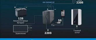
It is important to install a voltage stabilizer for the Baxi gas boiler, the presence of which will protect the device from power surges, short circuits and overheating. After connecting all the circuits, the technician performs the first startup and checks the quality of operation of the gas boiler he installed in the heating system.
If necessary, in order to increase the efficiency and economy of the device, the technician may recommend installing a room thermostat for the Baxi gas boiler, which will allow you to regulate the heating temperature of the coolant based on room temperature parameters
Error codes and causes of malfunctions of Baxi wall-mounted gas boilers
Summary list of fault indications for Baxi wall-mounted gas boilers equipped with a liquid crystal (LCD) display, models Eco Compact, Four Tech, Eco Four, Main Four, Main 5.
E01 (01E) - flame control sensor. Boiler blocking after three unsuccessful ignition attempts:
- There is no gas, the gas valve is closed, low pressure in the gas pipe.
- The phase and neutral wires of the electrical network for phase-dependent boiler models are mixed up.
- The ionization flame control electrode is faulty or dirty.
- The ignition unit or electrodes are faulty.
- The gas valve is faulty or incorrectly adjusted.
- Lack of air for gas combustion in the boiler burner
E02 (02E) - heating circuit temperature sensor. Overheating of the coolant in the heating circuit:
- Temperature sensor malfunction.
- Insufficient heat transfer to the sensor - it is recommended to apply thermal paste where the sensor body adheres to the adjacent part of the boiler.
- Insufficient coolant circulation through the heat exchanger due to pump malfunction or air in the system
E03 (03E) - draft sensor (thermostat in boilers with an open or pneumatic relay in boilers with a closed combustion chamber). Insufficient draft in the chimney or flue system:
- Traction sensor malfunction.
- Fan malfunction.
- Reducing the cross-section of a chimney or chimney.
Only for boilers with an open combustion chamber. As a result of the draft failure, the flue gas thermostat overheated and, as a result, an emergency shutdown of the boiler occurred. Check the chimney and whether it has the required draft.
Troubleshooting tips:
Check the chimney for the tightness of the seams and connectors, for compliance with the manufacturer’s recommendations for length and diameter, for the absence of obstacles in the smoke channel (clogging, icing), for blowing and backing of draft by the wind (for the location of the chimney head relative to the roof)
Check the free flow of air into the room where the boiler is installed. There must be an inlet from the street or from an adjacent room with windows.
For a boiler with an open combustion chamber, if the air comes directly from the street, then a supply ventilation opening of 8 cm2 per 1 kW of boiler power is sufficient, but not less than 200 cm2. If the air supply comes from an adjacent room of the building, then the minimum size of the supply ventilation opening should be determined at the rate of 30 cm2 per 1 kW of boiler power. The supply valve in the room with the boiler is installed at a height of no more than 30 cm from the floor. This could be a ventilation grille in the wall or door, or just a gap under the door.
Note: Electric hoods are prohibited in the boiler room.
Check the functionality of the flue gas thermostat.
E04 (04E) - flame control sensor. Frequent, more than six times, loss of flame on the burner:
- The reasons listed in E01 and E42 are
- Exhaust gases entering the boiler supply air duct.
E05 (05E) - heating circuit temperature sensor. No signal from the sensor:
- Malfunction of the heating circuit temperature sensor or open circuit with the electronic board.
E06 (06E) - DHW circuit temperature sensor. No signal from the sensor:
- Malfunction of the DHW circuit temperature sensor or open circuit with the electronic board.
E07 (07E) - NTC flue gas temperature sensor. No signal from the sensor:
- Faulty flue gas temperature sensor or open circuit with the electronic board.
E08 (08E) - electronic board. Error in flame control circuit:
- There is no grounding of the electronic board, there is no contact in the circuit between the board (connector X4) and the power supply box.
- Malfunction of the electronic control board.
E09 (09E) - electronic board. Gas valve safety circuit error:
- Faulty electronic control board.
E10 (10E) - minimum pressure switch for the heating circuit. Insufficient coolant pressure in the heating circuit:
- Check the pressure gauge readings and, if necessary, add water to the heating circuit.
- Minimum pressure switch faulty.
E12 (12E) - differential hydraulic pressure switch. There is no signal from the pressure switch:
- The circulation pump does not work.
- The heating system is contaminated.
- Insufficient coolant circulation (filter clogged, hydraulic resistance of the heating system is high).
- Malfunction of the pressure switch (membrane, microswitch, impulse tube)
E13 (13E) - differential hydraulic pressure switch. False signal from the pressure switch: stuck contacts of the pressure switch microswitch.
E22 (22E) - electronic board. Boiler shutdown due to low voltage in the electrical network, less than 162 V:
- The voltage in the electrical network does not meet the standard.
- The electronic board is faulty.
E25 (25E) - heating circuit temperature sensor. The rate of temperature increase in the heating circuit is more than 1 oC/sec:
- The circulation pump does not work.
- The heating system is contaminated.
- Insufficient coolant circulation (filter clogged, hydraulic resistance of the heating system is high).
- The heating circuit temperature sensor is faulty.
E26 (26E) - heating circuit temperature sensor. Exceeding the coolant temperature by more than 20 °C from the set one:
- The circulation pump does not work.
- The heating system is contaminated.
- Insufficient coolant circulation (filter clogged, hydraulic resistance of the heating system is high).
- The heating circuit temperature sensor is faulty.
E27 (27E) - DHW circuit temperature sensor. Incorrect sensor position:
- The DHW circuit temperature sensor is installed incorrectly.
- The DHW circuit temperature sensor is faulty.
E32 (32E) - temperature sensors for the DHW and heating circuits. Exceeding the heating temperature above 95 ° C twice in a row. Reducing the water temperature in the DHW circuit by 3 °C:
- Presence of scale in the bithermic heat exchanger.
- Malfunction of the NTC temperature sensor of the DHW circuit.
E35 (35E) - flame control sensor. Flame presence signal after the burner is turned off:
- The gas valve is faulty and does not completely shut off the gas supply.
- Moisture on the electronic board of the boiler.
- Interference coming from the electrical network. It is necessary to install a voltage stabilizer with galvanic isolation from the electrical network, and check the proper grounding of the boiler.
E36 (36E) - flue gas temperature sensor. The flue gas NTC sensor is faulty.
E40 (40E) – flue gas temperature sensor. GDC does not pass cyclic flue gas temperature tests:
- The flue gas NTC sensor is faulty.
- Obstruction of the chimney or air supply channel.
E41 (41E) - gas valve. GDC does not pass cyclic tests for ionization current:
- There is no gas, the gas valve is closed.
- The flame control electrode is faulty or dirty.
- Gas valve is faulty.
- Gas valve not calibrated.
E42 (42E) - fan. GDC fails initial tests. Boiler blocking after three unsuccessful attempts:
- The fan is faulty.
- Obstruction of the air supply channel.
E43 (43E) - electronic board. Blockage due to possible blockage of the air supply or too low gas pressure:
- Reasons described in E40 and E41.
- Inconsistency of the quality of supply electricity with the requirements of the standard (low voltage, interference)
E50 (50E) – NTC flue gas temperature sensor. Blockage due to flue gas temperature rising above 180 °C:
- Insufficient coolant circulation.
- The flue gas NTC temperature sensor is faulty.
E55 (55E) - gas valve. Gas valve not calibrated. It is necessary to perform calibration (parameters F45 and F48 of the service menu).
E62 (62E) - flame control electrode. Triggering of safety devices in the absence of stabilization of the flame signal or flue gas temperature:
- The flame control electrode is faulty or dirty.
- The NTC flue gas temperature sensor is faulty.
E65 (65E) - electronic board. Triggering of safety devices due to frequent, 10 times within 10 minutes, clogging of the air supply channel: reasons described in E40 and E41.
E96 (96E) - electronic board. Low voltage in the power supply network.
E97 (97E) - electronic board. The voltage frequency in the electrical network differs from 50 Hz.
E98 (98E) - electronic board. Internal error on the electronic board. Incorrect board parameter configuration:
- The parameters have not been configured depending on the boiler type.
- Parameters F03 and F12 of the service menu are set incorrectly.
- Electronic board malfunction.
E99 (99E) - electronic board. An internal error on the electronic board, which accumulates as a result of interference from the power supply network and leads to an independent reboot of the boiler.
The “exclamation mark within a triangle” icon flashes on the display . The boiler is operating at minimum power. The chimney/air duct is clogged or the gas inlet pressure is too low. To reset the fault, temporarily turn off the request for heat production from the heating or DHW system. If the problem persists, contact an authorized service center.
The “radiator” and “faucet” icons flash alternately on the display Scale has formed or the DHW temperature sensor is incorrectly positioned. Attach the clamp of the DHW temperature sensor to the pipe and check the contact with the temperature-sensitive element. Check the DHW temperature sensor (*). Check the primary heat exchanger for scale (when drawing water from the DHW circuit, the temperature of the domestic water leaving the boiler does not increase, while the temperature of the heating water supply to the heating circuit rises rapidly; in addition, the water flow is too low due to partial blockage heat exchanger).
DHW temperature sensor and heating supply temperature sensor: resistance value is about 10 kΩ at 25 °C (resistance decreases with increasing temperature). Flue gas temperature sensor: resistance value is approximately 49 kΩ at 25 °C (resistance decreases with increasing temperature).
More articles on this topic:
⇒ How to reduce the high gas consumption of a boiler for heating a house ⇒ DHW boiler for a double-circuit boiler or water heater ⇒ Setting the pressure in a heating system with a membrane expansion tank
More articles on this topic
- Installation and installation of windows in a private house with your own hands
- Cheap shallow foundation for a house in a swamp
- Solar collector - water heater for home, pool
- Snow load map
- Floors on the ground on the first floor of a private house without a basement
- How to properly insulate an attic
- How to remove old wallpaper from a wall or ceiling
- Bituminous shingles. Installation and laying of soft roofing
Baxi heating system wiring diagrams
The essence of the strapping is to prevent the device from overheating. This will give the properties of Baxi gas boilers simplicity and reliability in operation. Proper piping allows you to save money due to the effective distribution of heat energy.
And installing expensive automatic controls becomes irrelevant. If the owner is dealing with a solid fuel boiler that does not provide automation, then good piping contributes to the maximum efficient operation of the device. The correct piping scheme is a guarantee of efficient operation of the gas heating system.
These systems share:
- Two-pipe.
- Single-pipe.
- Combined.
Rice. 6 Combined circuit
Two-pipe Baksi circuit
It consists of a heating unit, expansion tank, etc. The system works in this way: the coolant is heated in the boiler, gas is supplied through the supply pipeline to the radiator, and the cooled coolant is returned to the unit through another pipeline (return). This is a classic diagram of a two-pipe heating system (Fig. 4).
You can find a diagram of the connection system with coolant supply in the same way as in the previous figure to each radiator. It is called a passing-cross scheme. And the return flow starts from the first radiator, and then, collecting all subsequent radiators, returns to the boiler - in the opposite direction. Thanks to this system, radiators heat up evenly.
Single-pipe diagram of the Baxi gas connection system (Fig. 5).
This type of piping of radiators with top filling. The water flows upward, where it connects with the radiators along the way. The coolant enters the radiator, passes through it and exits again into the same crowd. And so, having passed through all the radiators, the coolant finally enters the return pipeline. These systems are mainly suitable for apartment buildings. The disadvantage of such radiators is that the first radiators receive more heat than the next ones. The downside of the system is that it is not always suitable for large houses.
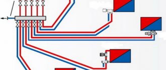
Combined diagram of the Baxi gas heating system (Figure 6).
If you look closely at the diagram, you will see that the system includes both a radiator system and a heated floor system. This allows you to make heated floors in a large house in the garage, bathroom, hallway, kitchen, and you can hang radiators in the living room and bedrooms. This system allows you to realize your desires and plans.
Rice. 7 Baxi boiler diagnostics
The circuit consists of a boiler, pump, expansion tank and piping system. The radiators are connected to the plumbing system. The coolant supply goes to the radiator, then to the second one and to the heated floor. The coolant returns from both the floor and the radiator into one pipe.
Connection diagrams for ZONT H-1, H-2, H-1V thermostats to BAXI boilers in OpenTherm mode
The batteries heat up in just a few minutes. In dual-circuit series, a three-stage valve changes the priority of domestic hot water and heating depending on the needs of the consumer. This is realized due to the fact that inside the tube through which liquid from the heating system flows, there is another tube of a smaller diameter through which tap water flows. Drain tap;
The video of the connection diagram for a double-circuit gas boiler shows that including a boiler in the system is not difficult. The system works in this way: the coolant is heated in the boiler, gas is supplied through the supply pipeline to the radiator, and the cooled coolant is returned to the unit through another return pipeline. Let's consider compact and convenient wall-mounted models that are popular on the market. You can connect a sensor that will measure the outside air temperature.
If the house is located next to a taller building, it may not be possible to achieve the necessary draft. All settings must be performed by service organizations.
Work on connecting the combustion product removal system: - the system connection unit consists of a vertical outlet into which the chimney adapter is inserted.
Fan; 3. It is important to know that the installation, and especially the connection of gas equipment, should be carried out only by experienced craftsmen who are able to carry out everything in compliance with the requirements and rules. Single-circuit boiler and indirect heating boiler, how to connect?
Read more: Standards for testing and measuring electrical equipment
Clogged systems
Dirt and deposits in the heating system can appear not only from the water supply (you need to install mesh filters there) or from the decomposition of antifreeze. Even when installing new elements and starting the system without flushing, the filters can become clogged: in the production of many elements of the heating system, various technological lubricants, powders, etc. are used. And their number can only increase during installation. Therefore, before powering the system and connecting it to the boiler, you need to flush it.
A similar procedure (flushing) should be carried out periodically - when replacing antifreeze or simply for preventive purposes.
Decoding
Parasitic flame - this is how the malfunction is described in the instructions for the boiler. Error E35 is not typical for Baksi, it is rare, and even experts find it difficult to accurately diagnose the equipment. On thematic forums, the emphasis is on the failure of the Baksi board, although failures are mainly caused by external factors: instability of power supply parameters, improper grounding, interference, and a number of others. The cost of the control unit reaches 30% of the price of the Baxi boiler, and if error E35 occurs, you do not need to immediately purchase a new board - the reason for the unit stopping is not necessarily its malfunction.
Baxi boiler control board
Characteristics of Baxi eco four 24
The eco gas boiler is a double-circuit wall-mounted boiler with an automatic control system. The number 24 indicates the maximum developed thermal power in kW (minimum - 9 kW). At the same time, the maximum power consumption of the electrical network is 25.8 kW, and the largest heating area is 240 square meters. If the gas boiler is also marked with the index F, it will be equipped with a turbine for supplying air and a coaxial pipe for exhaust gases to exit the house. It is good to buy such a boiler when there is no chimney in the house, or a boiler cannot be connected to it, or if you live in an apartment.
As the instructions say, the Baksi Ecofor 240 gas boiler has the following main characteristics.
- It has the function of continuous electronic modulation, independent regulation of its power, depending on the temperature, according to the specified parameters. In other words, you set the required coolant temperature and hot water temperature (DHW) using the keys, and the boiler maintains it in such a way that the clocking (frequency of switching on and off) of the boiler is minimal.
- When operating in heating mode, the smooth electronic ignition function operates. The equipment reaches the specified maximum power gradually, at a minimum flame, which reduces the noise from its operation.
- Availability of flame dividers made of stainless steel.
- An original system for supplying the air necessary for combustion.
- Possibility of working on liquefied gas after reconfiguration.
- The heat exchange device is bithermal. This means that in one thermomechanical device, both OM (coolant water) and DHW flow through two different pipe systems made according to the appropriate design.
- The circulation pump is designed in an energy-saving mode, with automatic removal of air from the system.
- The presence of a filter on the DHW supply water pipeline to remove suspended particles. This filter will not protect the pipes from damage from the inside if the water is too hard. If the amount of hardness salts in the water exceeds 20º F, you will have to purchase additional water softening equipment, for example, purchase a polyphosphate dispenser.
- Pump post-circulation. This function is available for eco for 240 if a thermostat is connected. In a room where it is necessary to maintain a certain microclimate, a thermostat device is mounted on the wall at a level of 1.5 m and connected via wires to the corresponding terminals on the eco boiler. The required maximum temperature is set, upon reaching which the gas supply will turn off on its own, but the pump will continue to circulate the coolant through the pipes for another three minutes, then it will turn off.
- The gas boiler of this modification has a self-diagnosis function. If there is a malfunction, the automation itself determines the probable cause and displays an error code on the electronic display. By looking at the instructions, you can find out what malfunction this code corresponds to.
- The ability to configure one of two main modes for regulating the temperature of the coolant: normal (35-80 degrees) and mode (35-45 degrees), which helps save energy when there is a “warm floor”.
- Anti-icing system. If the boiler has been turned off for a long time and the temperature drops to critical, the automation will automatically turn on the burners and the circulation pump, which will protect the entire system from freezing. This function will operate in any mode (“winter”, “summer”), unless the power supply is turned off.
- You can connect a sensor that will measure the outside air temperature.
- Displaying water temperature on the display screen.
- Possibility of connecting a timer that can be programmed.
- Flame control ionized.
- Sensor for monitoring the vacuum at the outlet of combustion products from the boiler.
- The gas boiler has a kind of inspector of normal operating conditions - a pressure switch that turns off the gas supply when the water pressure drops, which is additional protection against overheating of equipment elements.
In the photo you can see the location of the various parts under the cover.
Immergas boiler clocking and power
Brand and model of equipment:
Immergas Eolo Star 24 kV
David:
Hello. I really need your advice. I re-read and reviewed a bunch of material, but still did not find an answer to my question. Immergaz Eolo Star 24-kilowatt boiler, CO 4 panel radiators with a total power of 7500 watts and a dryer in the bathroom, about 40 liters of coolant in the system.
A room thermostat is installed. The coolant temperature is 75 degrees. Boiler operation: after the thermostat turns off the boiler, there is a pause of about 2 hours, the water in the system cools down to 24-30 degrees and after the thermostat closes the contacts, the boiler turns on and runs for 5 minutes at minimum power and gradually increases to maximum until the water reaches 75 degrees.
Then it modulates to a minimum (set to 45%) and manages to cycle twice before the thermostat works. In the menu I lowered the power to 5% and the boiler stopped clocking
I can’t understand this: when working with a thermostat, in my opinion it is important that the boiler heats the apartment faster and that the apartment maintains the temperature longer
The passport states that the minimum heating power is 11.5 kilowatts. Which is more profitable from the point of view of gas consumption: rapid heating of the coolant and then operating at a minimum to maintain the temperature. The manufacturer does not recommend lowering the power below 30 percent due to a decrease in efficiency. What is more important: a decrease in efficiency or operation of the boiler without clocking?
Answer:
Hello David. My opinion is that clocking is definitely bad for any unit, including a boiler. Clocking leads to additional wear of components and, as a result, to excessive fuel consumption and a reduction in the service life of the boiler. In addition, there are thermal shocks in CO, the danger of overheating of the coolant and other troubles associated with improper operation of heating equipment...
There can be only one reason for the boiler clocking - insufficiently efficient operation of the entire CO. In this case, there can only be two reasons:
- incorrect calculation;
- incorrect installation of CO.
However, not a single heating engineer can take into account all the nuances when creating a CO...
As an option, you can install a modulating burner - a burner with variable power. But this is a “half” solution. It is better to install an additional tank for the coolant - a heat accumulator between the boiler and the CO. It will serve as a compensator for temperature changes.
The boiler “pumps” heat into the heat accumulator, and the CO uses this heat as needed (needed). Everything is very simple. Personally, I have 200 liters and there are no problems with timing).
If you have any questions, write.
Error E01
The most typical malfunction of a boiler from absolutely any manufacturer, which is probably why it is indicated by the first serial number. Error E01 occurs when it is impossible to ignite the boiler gas burner normally. Ignition is controlled by a special device - a flame ionization sensor (or a flame presence electrode). In some boiler models it can be combined in one electrode (for example, in ECOFOUR), in others - separately. This electrode records microcurrents that arise precisely during gas combustion between the electrode and the burner. Normal gas combustion corresponds only to a certain microcurrent value, therefore, if the control board detects deviations from the nominal values, error E01 will appear and the boiler will stop.
Therefore, the cause of error E01 can be either improper gas combustion:
- insufficient pressure at the outlet of the gas valve
- lack of gas supply
- insufficient air supply to the combustion chamber
or malfunction of actuators:
- state of the flame control electrode (position relative to the burner, contamination)
- connection of the sensor to the control unit
- failure of the control board (ignition unit)
In most cases, the user will be able to independently check only the position and condition of the ionization sensor (the gap size is given in the instructions for each model) and try to reset the error (on Baxi boilers, hold down the R button for more than 2 seconds).
To adjust the gas valve or diagnose the electronic board of the boiler, you will need the help of a qualified specialist, because it is performed using a special device - a differential pressure gauge.
There are cases when it is possible to visually determine fault E01. Watch the video below; with the lid open, you can see why the boiler cannot start: apparently the insulation of the electrode supply wire was broken and the spark struck in the wrong place where it was necessary:
The board is the very last device on the list because it is diagnosed after all other possible causes of error E01
. This is a technically complex electronic device, the diagnosis of which requires special knowledge and equipment, and there are not many specialists who can carry out repairs.
If you are immediately offered to buy a new board, I recommend reading our material on repairing baxi electronic boards. Most likely you will be able to save a decent amount of money.
How do Baksi double-circuit boilers work?
Baxi double-circuit boilers are designed to heat water in the heating and hot water circuits. In fact, such units are an improved single-circuit modification, implemented with a DHW boiler in the form of a conventional or bithermal heat exchanger. In the first case, heat transfer in the DHW circuit occurs by heated coolant coming from the heating boiler.
The bithermal heat exchanger does not differ from the outside of a standard boiler heating boiler. Only inside the heating surfaces for heating and domestic hot water are separated by tubes of a complex configuration, similar to a rhombus.
Water flows along the outer contour for heating, and inside the diamond for hot water supply. This design more effectively removes heat from the heating medium, but has problems when cleaning surfaces from scale.
Therefore, for such devices it is mandatory to install filters for preliminary purification of make-up water with a softening function.
Construction of Baksi boilers
Let's look at the basic design of the Baxi boiler. The basic diagram is printed in the operating instructions for each specific model, but the main components will be the same.
There is a chimney at the top. Immediately below it there is a fan with a Venturi tube and an exhaust hood for removing combustion products. Below is the primary heat exchanger, which looks like a radiator and coil, a little to the left is a safety thermostat and an NTC heating temperature sensor.
In the center there is a combustion chamber, inside which there is a burner and electrodes for ignition and ionization of the flame. A gas train with nozzles is connected to the modulation burner, into which gas flows from the gas valve.
On the right side, a pipe goes down from the heat exchanger, connected to the expansion tank and circulation pump. The pump is equipped with an automatic air bleed valve. It ends at the bottom with a tap for draining the coolant from the apparatus and a pressure gauge; it receives water from the heating system of the house.
A pipe is lowered on the left side, on which a hydraulic pressure switch is installed and a safety valve at the end. Water comes out of it into the heating system. These pipes are connected to each other by an automatic bypass.
In double-circuit models, a secondary plate heat exchanger, a DHW priority sensor and a three-stage valve are additionally installed. The Baxi Luna 3 Combi and Nulova 3 model series are equipped with a small-volume indirect boiler.
Main 5 boilers are equipped with a bithermic heat exchanger, which simultaneously heats both running water and coolant. This is realized due to the fact that inside the tube through which liquid from the heating system flows, there is another tube of a smaller diameter through which tap water flows.
An electronic control board is installed on the front. The electrical diagram printed in the operating manual shows where all the boiler elements and sensors are connected to. Using it you can understand how the electrical part of the equipment works.
A steel casing is installed outside, on which there is an electrical control panel with power buttons and operating mode selection buttons. Modern models are equipped with a display to display technical data and error codes in the event of a malfunction.
Two ways to drain water from the boiler, pros and cons
So, there are two ways to drain the water from the boiler without flooding everything around it.
Method one
For example, through a safety valve, one that is designed to relieve excess pressure.
Relief valve
This is convenient because the relief valve is located in the front part of the boiler, and it is easy to access; you just need to place some container and turn the red handle of the tap to release the water.
It also has a nozzle that can be easily rotated to direct the draining water into the container. But it’s even better to do all this through a hose, and you don’t have to pull it onto the nozzle, you can just hold it. But this method also has a drawback. The fact is that this tap is usually at rest for a long time and its rubber gasket is deformed when it is strongly pressed against the ribs of the body. Therefore, if this whole thing gets started, then there is a high probability that after filling the boiler with water, the relief valve will begin to leak and there will be a need to disassemble, repair or replace it.
Method two
Use the tap to drain the water. It does not have the disadvantage described above, since it is intended specifically for this purpose, but the disadvantage is the location of this very crane. It is located at the rear wall of the boiler, from below and is not always accessible, since boilers are often installed in various cabinets.
Water drain tap
In this case, you will have to use a hose unless you want to drain the water onto the floor. But it is also not necessary to pull the hose tightly onto the outlet; simply loosen the faucet valve (the ribbed part) by rotating it counterclockwise, and simply direct the water through the hose into the container, holding the hose with your hand.
Drain the water using a hose
Well, now that the work is completed, do not forget to close the drain valve before filling the circuit with water!
Good luck!
Installation of a Baxi gas boiler
Boiler installation consists of several stages:
- Installing a water filter on the pipeline supplying water to the hot water system. It is imperative to install shut-off valves on both sides, making it possible to dismantle the filter for maintenance, repair or replacement.
- Place the unit in the designated area. Floor-standing units are simply placed at the desired point in the room, while wall-mounted boilers are hung on the surface of solid walls. Mounting to plasterboard partitions or other structures that do not have sufficient load-bearing capacity is prohibited. Mounting to the wall is done using special brackets (sleds), which are included in the delivery set.
- All supply pipelines are connected - gas, forward and return coolant, hot water supply. A coaxial chimney is installed and connected (some models are equipped with a double vertical chimney). The presence and quality of traction is immediately checked.
The final stage is connecting the boiler to the power supply network. This requires a separate outlet; powering other devices from it is prohibited by operating rules.
IMPORTANT! It is strongly recommended to use a stabilizer to eliminate voltage surges.
Savings and regular equipment maintenance
The basic structure of a traditional gas boiler is almost the same, regardless of the manufacturer. Thermal energy from gas combustion is transferred to the coolant through a heat exchanger. There can be either one or two heat exchangers in the boiler. During operation of any gas boiler, the heat removal surface becomes contaminated with soot deposits from the outside and scale from the inside.
From practice, we can say that it is extremely rare that the system is filled with special prepared water or the water supply system is equipped with a water treatment system. This is especially true for apartment buildings, in which the owners receive a ready-made heating system along with the apartment.
Therefore, annual regular maintenance will definitely affect the efficiency of equipment operation for the better! This especially applies to boilers with bithermic heat exchangers, which, due to their design, are difficult to clean.
Baxi gas heating appliances are easy to use and economical in fuel consumption. However, much depends on how the Baxi gas boiler is configured. You should know how to adjust your unit so that it consumes a minimum of fuel and at the same time ensures a comfortable room temperature.
Baxi heating system wiring diagrams
Despite the fact that the manufacturer has taken care to provide the user with all the necessary documentation for connecting the boiler to the heating system, in order to maintain warranty obligations, it is not recommended to do this yourself; you need to invite a service department, which will be recommended in the store when purchasing the unit.
Thus, the user’s task will be to select the desired strapping pattern. It will depend on the installed heating circuit. According to existing heat supply schemes, it can be:
- two-pipe for houses with a large heating area;
- single-pipe with natural circulation for houses with small heated area;
- combined, for multi-circuit heating systems.
Two-pipe scheme
The two-pipe Baksi circuit is made from a heating source, a circulation pump, an expansion tank, a safety group, a mud trap and a coolant purification filter.
The principle of operation of a two-pipe network:
- Cold water enters the heating circuit through the filter to the suction of the network pump.
- Water enters the boiler and is heated to the temperature set by the user on the operating panel.
- The heated coolant is supplied to the heating system.
- From the supply pipeline there are branches to each heating device.
- Cooled water from the radiator flows through the return branch into the common return line and is pumped into the unit for the next heating cycle
Air vents and a heat sensor are installed on the heating device, which regulates the coolant depending on the set temperature.
Thanks to this scheme, the radiators heat up evenly and, if necessary, can be completely individually switched off.
Single-pipe scheme
A single-pipe scheme with natural circulation is an affordable and economical piping scheme designed for small-sized one-story houses.
The scheme is as follows:
- The gas boiler is installed on the wall in the kitchen.
- The supply from the device comes through one pipeline, to which all radiators are connected in series.
- The heated coolant from the device enters the supply line, which has an upper distribution, and then sequentially passes through all the heating radiators.
- From the last radiator it flows into the return line and then into the boiler for a new heating cycle.
- The movement of the medium occurs under the influence of natural circulation that occurs due to the temperature difference in the supply and return. For efficient movement, the supply and return pipelines are installed with a slope. The vent is installed at the highest point, usually in the attic.
- An expansion tank is installed in the system to compensate for the thermal expansion of the coolant.
The disadvantage of this scheme is that the first batteries along the coolant flow are overheated, and the last ones are underheated. The efficiency of the circuit can be increased by integrating a circulation pump into the circuit, which will increase the heating area from 40 m2 to 150 m2.
Combined diagram of the Baxi gas heating system
This is the most progressive boiler piping scheme; it has several independent heating circuits - a radiator and a “warm floor” system.
Typically, radiators are installed in bedrooms and the living room, and in other rooms in the kitchen, bathroom and other utility rooms, “warm floors” are installed, which operate at lower temperature conditions and can work with reverse coolant.
The return coolant temperature limitation is set by the manufacturer for a specific unit model in order to counteract the formation of condensation in the flue gases. To distribute the coolant across different circuits, you will need to install a Baxi boiler with a hydraulic manifold and separate circulation pumps for each circuit.
Filling the heating system with water
Starting a gas boiler begins with filling the heating system with water. Everything is simple here - modern double-circuit boilers do not require the installation of a special system feeding unit. It is already built into the boiler and equipped with a special tap, which, as a rule, is located at the bottom of the boiler in close proximity to the cold water connection pipe. Open the feed tap and slowly fill the system with water.
Starting the boiler - how to fill the system with water
A very important point in the operation of any boiler equipment is fluid pressure. To control this parameter of the heating system, almost all boilers are equipped with a pressure gauge. During the process of filling systems with water, it is necessary to monitor the pressure and after it reaches 1.5-2 atm, filling the system will need to be stopped. In principle, the operating pressure of a boiler may vary depending on the manufacturer and model - therefore, see the instructions for the boiler for the exact operating pressure.
Do-it-yourself first start-up of a gas boiler