Using hydraulic calculations, you can select the correct diameters and lengths of pipes, and correctly and quickly balance the system using radiator valves. The results of this calculation will also help you choose the right circulation pump.
As a result of the hydraulic calculation, it is necessary to obtain the following data:
m is the coolant flow rate for the entire heating system, kg/s;
ΔP - pressure loss in the heating system;
ΔP1, ΔP2... ΔPn, - pressure loss from the boiler (pump) to each radiator (from the first to the nth);
Coolant flow
Coolant flow is calculated using the formula:
,
where Q is the total power of the heating system, kW; taken from the calculation of heat loss of the building
Cp—specific heat capacity of water, kJ/(kg*deg.C); for simplified calculations we take it equal to 4.19 kJ/(kg*deg.C)
ΔPt—temperature difference between inlet and outlet; We usually take the boiler flow and return
Coolant flow calculator (water only)
Q = kW; Δt = oC; m = l/s
In the same way, you can calculate the coolant flow on any section of the pipe. The sections are selected so that the water velocity in the pipe is the same. Thus, the division into sections occurs up to the tee, or before the reduction. It is necessary to sum up the power of all radiators to which the coolant flows through each section of the pipe. Then substitute the value into the formula above. These calculations must be made for the pipes in front of each radiator.
Specific calculations
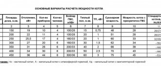
Let's say you need to make a calculation for a household with an area of 150 square meters. m. If we assume that 100 watts of heat are lost per 1 square meter, we get: 150x100 = 15 kW of heat loss.
How does this value relate to the circulation pump? With heat losses, there is a constant consumption of thermal energy. To maintain the temperature in the room, more energy is required than to compensate for it.
To calculate a circulation pump for a heating system, you should understand what its functions are. This device performs the following tasks:
- create a water pressure sufficient to overcome the hydraulic resistance of the system components;
- pump through pipes and radiators the volume of hot water required to effectively warm up the household.
That is, in order for the system to work, you need to adjust the thermal energy to the radiator. And this function is performed by the circulation pump. It is this that stimulates the supply of coolant to heating devices.
The next task: how much water, heated to the required temperature, must be delivered to the radiators over a certain period of time, while compensating for all heat loss? The answer is expressed in the amount of coolant pumped per unit time. This will be called the power that the circulation pump has. And vice versa: you can determine the approximate coolant flow rate based on the pump power.
Data needed for this:
- The amount of thermal energy required to compensate for heat loss. For this household with an area of 150 sq. meters this figure is 15 kW.
- The specific heat capacity of water, which acts as a coolant, is 4200 J per 1 kilogram of water, for every degree of temperature.
- Temperature delta between the water supply from the boiler and the last section of the return pipeline.
It is believed that under normal conditions this last value does not exceed 20 degrees. On average they take 15 degrees.
The formula for calculating the pump is as follows: G/(cx(T1-T2))= Q
- Q is the coolant consumption in the heating system. So much liquid at a certain temperature must be delivered to the circulation pump to the heating devices per unit of time in order for heat loss to be compensated. It is not advisable to purchase a device that has more power. This will only lead to increased electricity consumption.
- G - heat loss at home;
- T2 is the temperature of the coolant flowing from the boiler heat exchanger. This is exactly the temperature level that is needed to heat the room (about 80 degrees);
- T1 - temperature of the coolant in the return pipeline at the entrance to the boiler (most often 60 degrees);
- c is the specific heat capacity of water (4200 Joules per kg).
When calculated using the above formula, the figure is 2.4 kg/s.
Now we need to translate this indicator into the language of circulation pump manufacturers.
1 kilogram of water corresponds to 1 cubic decimeter. One cubic meter is equal to 1000 cubic decimeters.
It turns out that the pump pumps the following volume of water per second:
- 2.4/1000=0.0024 cubic meters m.
Next you need to convert seconds to hours:
- 0.0024x3600=8.64 cubic meters m/h.
Coolant speed
Then, using the obtained coolant flow values, it is necessary for each section of pipes in front of the radiators to calculate the speed of water movement in the pipes using the formula :
,
where V is the coolant movement speed, m/s;
m is the coolant flow through the pipe section, kg/s
ρ—density of water, kg/cub.m. can be taken equal to 1000 kg/cub.m.
f - cross-sectional area of the pipe, sq.m. can be calculated using the formula: π * r2, where r is the internal diameter divided by 2
Coolant velocity calculator
m = l/s; pipe mm by mm; V = m/s
Features of calculating heating systems with thermostatic valves
- Technical support
- Articles
- Features of calculating heating systems with thermostatic valves
#automation of engineering systems #design #installation #adjustment
Thermostatic radiator valves have special hydraulic design features compared to manual radiator valves. These features are related to the specific operation of the valve in the heating system.
These valves are controlled by a heat-sensitive element (thermal head), inside of which there is a bellows container filled with a working fluid (gas, liquid, solid) with a high coefficient of volumetric expansion. When the temperature of the air surrounding the bellows changes, the working fluid expands or contracts, deforming the bellows, which, in turn, acts on the valve stem, opening or closing it ( Fig. 1
).
Rice. 1. Thermostatic valve operation diagram
The main hydraulic characteristic of a thermostatic valve is the flow capacity Kv
.
This is the water flow that the valve can pass through when the pressure drop across it is 1 bar. The index “ V
” means that the coefficient is related to the hourly volumetric flow rate and is measured in m3/h. Knowing the valve capacity and water flow through it, you can determine the pressure loss across the valve using the formula:
ΔP _
k = (
V
/
K
v)2 · 100, kPa.
Control valves, depending on the degree of opening, have different flow capacities. The capacity of a fully open valve is indicated by Kvs
.
Pressure loss on a thermostatic radiator valve during hydraulic calculations, as a rule, is determined not at full opening, but for a certain proportionality zone - X
p.
X
p is the operating zone of the thermostatic valve in the range from the air temperature at full closure (point S on the control graph) to the user-set value of the permissible temperature deviation.
For example, if the Kv
is given at
X
p =
S
– 2, and the thermocouple is installed in such a position that at an air temperature of 22 ˚C the valve will be completely closed, then this coefficient will correspond to the position of the valve at an ambient temperature of 20 ˚C.
From this we can conclude that the air temperature in the room will fluctuate between 20 and 22 ˚С. Xp indicator
affects the accuracy of temperature maintenance.
At Xp
= (
S
– 1), the range of maintaining the internal air temperature will be within 1 ˚С.
At Xp
= (
S
– 2) – range 2 ˚С.
Zone X
p = (
S
– max) characterizes the operation of the valve without a temperature-sensitive element.
In accordance with GOST 30494-2011 “Residential and public buildings. Indoor microclimate parameters”, during the cold season in the living room, the optimal temperatures range from 20 to 22 ˚С, that is, the range of temperature maintenance in the residential premises of buildings should be 2 ˚С. Thus, to calculate residential buildings, it is necessary to select the throughput values at Xp
= (
S
– 2).
Rice. 2. Thermostatic valve VT.031
In Fig. 3
The results of a bench test of the thermostatic valve VT.031 (
Fig. 2
) with a thermostatic element VT.5000 with the value set to “3” are shown.
Point S
on the graph is the theoretical closing point of the valve. This is the temperature at which the valve has such low flow that it can be considered practically closed.
Rice. 3. Closing schedule of valve VT.031 with thermoelement VT.5000 (item 3) at a pressure difference of 10 kPa
As can be seen in the graph, the valve closes at a temperature of 22 °C. As the air temperature decreases, the valve capacity increases. The graph shows the water flow through the valve at a temperature of 21 ( S
– 1) and 22 (
S
– 2) ˚С.
In table 1
The passport values of the throughput of the thermostatic valve VT.031 are presented at various
Xp
.
Table 1. Nameplate values of valve capacity VT.031
| Valve DN | 1/2» | |
| Coefficient value bandwidth Kv at | S – 1 | 0,35 |
| S – 1,5 | 0,45 | |
| S – 2 | 0,63 | |
| S – 3 | 0,9 | |
| Kvs ; m3/h | 1,2 | |
The valves are tested on a special stand shown in Fig. 4
. During the tests, a constant pressure drop across the valve is maintained at 10 kPa. The air temperature is simulated using a thermostatic bath of water into which the thermal head is immersed. The temperature of the water in the bath gradually increases, and the flow of water through the valve is recorded until it is completely closed.
Rice. 4. Bench testing of valve VT.032 for flow capacity in accordance with GOST 30815-2002
In addition to throughput values, thermostatic valves are characterized by such an indicator as maximum pressure drop. This is such a pressure drop across the valve at which it maintains its passport control characteristics, does not create noise, and also at which all valve elements will not be subject to premature wear.
Depending on the design, thermostatic valves have different maximum pressure drop values. For most thermostatic radiator valves on the market, this characteristic is 20 kPa. At the same time, according to clause 5.2.4 of GOST 30815-2002, the temperature at which the valve closes at a maximum pressure drop should not differ from the closing temperature at a pressure difference of 10 kPa by more than 1 ˚C.
From the graph in Fig. 5
it can be seen that valve VT.031 closes at 22 ˚C with a pressure drop of 10 kPa and thermoelement setting “3”.
Rice. 5. Closing graphs of valve VT.031 with thermocouple VT.5000 at a pressure drop of 10 kPa (blue line) and 100 kPa (red line)
With a pressure difference of 100 kPa, the valve closes at a temperature of 22.8˚C. The influence of differential pressure is 0.8 ˚C. Thus, in real operating conditions of such a valve with pressure drops from 0 to 100 kPa, when setting the thermoelement to the number “3”, the valve closing temperature range will be from 22 to 23 ˚C.
If, under real operating conditions, the pressure drop across the valve increases above the maximum, the valve may create unacceptable noise, and its characteristics will differ significantly from the specifications.
What causes an increase in the pressure drop across a thermostatic valve during operation? The fact is that in modern two-pipe heating systems, the coolant flow in the system is constantly changing, depending on the current heat consumption. Some thermostats open, some close. Changes in flow rates across sections lead to changes in pressure distribution.
For example, consider the simplest circuit ( Fig. 6
) with two radiators. A thermostatic valve is installed in front of each radiator. There is a control valve on the common line.
Rice. 6. Design diagram with two radiators
Let us assume that the pressure loss on each thermostatic valve is 10 kPa, the pressure loss on the valve is 90 kPa, the total coolant flow is 0.2 m3/h and the coolant flow through each radiator is 0.1 m3/h. We neglect pressure losses in pipelines. The total pressure loss in this system is 100 kPa and is maintained at a constant level. The hydraulics of such a system can be represented by the following system of equations:
where V
o - total flow rate, m3/h,
V
r - flow rate through radiators, m3/h,
kv
c - valve capacity, m3/h,
kv
because
– flow capacity of thermostatic valves, m3/h, Δ P
in – pressure drop across the valve, Pa, Δ
P
because – pressure drop across the thermostatic valve, Pa.
Rice. 7. Design diagram with the radiator turned off
Let's assume that in the room where the upper radiator is installed, the temperature has increased and the thermostatic valve has completely blocked the flow of coolant through it ( Fig. 7
). In this case, all flow will go only through the lower radiator. The pressure drop in the system is expressed by the following formula:
where Vo′ is the total flow rate in the system after turning off one thermostatic valve, m3/h, Vp′ is the coolant flow rate through the radiator, in this case it will be equal to the total flow rate; m3/h.
If we take into account that the pressure drop is maintained constant (equal to 100 kPa), then we can determine the flow rate that will be established in the system after one of the radiators is turned off.
The pressure loss at the valve will decrease, since the total flow through the valve has decreased from 0.2 to 0.17 m3/h. On the contrary, the pressure loss on the thermostatic valve will increase, because the flow through it has increased from 0.1 to 0.17 m3/h. The pressure loss across the valve and thermostatic valve will be:
From the above calculations we can conclude that the pressure drop across the thermostatic valve of the lower radiator when opening and closing the thermostatic valve of the upper radiator will vary from 10 to 30.8 kPa.
But what happens if both valves block the flow of coolant? In this case, the pressure loss at the valve will be zero, since there will be no movement of coolant through it. Therefore, the pressure difference before the spool/after the spool in each radiator valve will be equal to the available pressure and will be 100 kPa.
If valves with a permissible pressure drop less than this value are used, the valve may open despite there being no real need to do so. Therefore, the pressure drop in the regulated section of the network must be lower than the maximum permissible pressure drop on each thermostat.
Let's assume that instead of two radiators, a certain number of radiators are installed in the system. If at some point all the thermostats, except one, close, then the pressure loss across the valve will tend to 0, and the pressure drop across the open thermostatic valve will tend to the available pressure, i.e., for our example, 100 kPa.
In this case, the coolant flow through the open radiator will tend to the value:
That is, in the most unfavorable case (if only one of the many radiators remains open), the flow rate on the open radiator will increase more than three times.
How much will the power of the heating device change with such an increase in flow? Heat transfer Q
sectional radiator is calculated according to the formula:
where Q
n – rated power of the heating device, W, Δ
t
av – average temperature of the heating device, °C,
t
in – internal air temperature, °C,
V
pr – coolant flow through the heating device,
n
– coefficient of dependence of heat transfer on the average temperature of the device,
p
– coefficient of dependence of heat transfer on coolant flow.
Let us assume that the heating device has a rated heat output Q
n = 2900 W, design parameters of the coolant 90/70 ˚С.
The coefficients for the radiator are accepted: n
= 0.3, p = 0.015. During the calculation period, at a flow rate of 0.1 m3/h, such a heating device will have the following power:
To find out the power of the device at Vр''=0.316 m³⁄h, it is necessary to solve the system of equations:
Using the method of successive approximations, we obtain a solution to this system of equations:
From this we can conclude that in a heating system, under the most unfavorable conditions, when all heating devices except one in the area are closed, the pressure drop across the thermostatic valve can increase to the available pressure. In the example given, with an available pressure of 100 kPa, the flow rate will increase three times, while the power of the device will increase by only 17%.
Increasing the power of the heating device will lead to an increase in the air temperature in the heated room, which, in turn, will cause the thermostatic valve to close. Thus, fluctuations in the pressure drop across the thermostatic valve during operation within the specified maximum differential value are acceptable and will not lead to disruption of the system.
In accordance with GOST 30815-2002, the maximum pressure drop across the thermostatic valve is determined by the manufacturer based on compliance with the requirements of noiselessness and maintaining control characteristics. However, manufacturing a valve with a wide range of permissible pressure drops is associated with certain design difficulties. Special requirements are also placed on the precision of manufacturing of valve parts.
Most manufacturers produce valves with a maximum pressure drop of 20 kPa.
An exception is the VALTEC VT.031 and VT.032 valves (direct thermostatic valve) with a maximum pressure drop of 100 kPa ( Fig. 8
) and valves from Giacomini series R401–403 with a maximum pressure drop of 140 kPa (
Fig. 9
).
Rice. 8. Technical characteristics of radiator valves VT.031, VT.032
Rice. 9. Fragment of the technical description of the thermostatic valve Giacomin R403
Rice. 10. Fragment of the technical description of the thermostatic valve
When studying technical documentation, you need to be careful, as some manufacturers have adopted the practice of bankers - inserting small text in notes.
In Fig. 10
a fragment from the technical description of one of the types of thermostatic valves is presented. The main column indicates a maximum pressure drop of 0.6 bar (60 kPa). However, there is a note in the footnote that the actual operating range of the valve is limited to only 0.2 bar (20 kPa).
Rice. 11. Thermostatic valve spool with axial seal fastening
The restriction is caused by noise generated in the valve at high pressure drops. As a rule, this concerns valves with an outdated spool design, in which the sealing rubber is simply attached in the center with a rivet or bolt ( Fig. 11
).
With large pressure drops, the seal of such a valve begins to vibrate due to incomplete contact with the spool plate, causing acoustic waves (noise).
The increased permissible pressure drop in VALTEC and Giacomini valves is achieved due to a fundamentally different design of spool assemblies. In particular, VT.031 valves use a brass spool plunger, “lined” with EPDM elastomer ( Fig. 12
).
Rice. 12. View of the valve spool assembly VT.031
Nowadays, the development of thermostatic valves with a wide range of operating pressure drops is one of the priorities of specialists at many companies.
- Based on the above, the following recommendations can be given for the design of heating systems with thermostatic valves:
- It is recommended to determine the capacity coefficient of a thermostatic valve based on the permissible temperature range of the room being served. For example, for living rooms according to GOST 30494-2011, the optimal parameters of internal air are in the range of 20–22 ˚С. The value of Kv in this case is taken at Xp = S – 2. In rooms of category 3a (rooms with large numbers of people, in which people are mainly in a sitting position without outdoor clothing), the optimal temperature range is 20–21 ˚С. For these rooms, the Kv value is recommended to be taken at Xp = S – 1.
- Devices (bypass valves or differential pressure regulators) must be installed on the circulation rings of the heating system to limit the maximum pressure drop so that the pressure drop across the valve does not exceed the maximum rated value.
Let us give several examples of the selection and installation of devices to limit the pressure drop in the area with thermostatic valves.
Example 1.
The calculated pressure loss in an apartment heating system (
Fig. 13
), including thermostatic valves, is 15 kPa. The maximum pressure drop across thermostatic valves is 20 kPa (0.2 bar). The pressure loss on the collector, including losses on heat meters, balancing valves and other fittings, will be taken as 8 kPa. As a result, the pressure drop to the collector is 23 kPa.
If you install a differential pressure regulator or bypass valve before the manifold, then if all thermostatic valves in this branch are closed, the difference across them will be 23 kPa, which exceeds the rated value (20 kPa). Therefore, in this system, a differential pressure regulator or bypass valve must be installed at each outlet after the manifold, and must be set to a differential of 15 kPa.
Rice. 13. Scheme for example 1
Example. 2
.
If we adopt a radial apartment heating system rather than a dead-end system ( Fig. 14
), then the pressure loss in it will be significantly lower. In the given example of a collector-beam system, the losses in each radiator loop are 4 kPa. Let us assume that the pressure loss on the apartment manifold is 3 kPa, and the pressure loss on the floor manifold is 8 kPa.
In this case, the differential pressure regulator can be placed in front of the floor collector and set to a differential of 15 kPa. This scheme allows you to reduce the number of differential pressure regulators and significantly reduce the cost of the system.
Rice. 14. Scheme for example 2
Example 3.
This option uses radiator thermostatic valves with a maximum pressure drop of 100 kPa (
Fig. 15
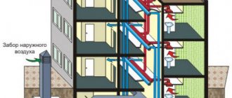
). As in the first example, we assume that the pressure loss in the apartment heating system is 15 kPa. Pressure loss at the apartment input unit (apartment station) is 7 kPa. The pressure drop in front of the apartment station will be 23 kPa. In a ten-story building, the total length of a pair of heating system risers can be taken to be about 80 m (the sum of the supply and return pipelines).
Rice. 15. Scheme for example
With an average linear pressure loss along the riser of 300 Pa/m, the total pressure loss in the risers will be 24 kPa. It follows that the pressure drop at the base of the risers will be 47 kPa, which is less than the maximum permissible pressure drop across the valve.
If you install a differential pressure regulator on a riser and set it to a pressure of 47 kPa, then even when all the radiator valves connected to this riser are closed, the pressure drop across them will be below 100 kPa.
Thus, you can significantly reduce the cost of the heating system by installing instead of ten differential pressure regulators on each floor, one regulator at the base of the risers.
Author: Zhigalov D.V.
Print the article: Features of calculating heating systems with thermostatic valves
“twist
© Copyright holder Vesta Regions LLC, 2010 All copyrights reserved. When copying an article, a link to the copyright holder and/or to the website www.valtec.ru is required.
Pressure loss at local resistances
Local resistance on a pipe section is the resistance on fittings, fittings, equipment, etc. Pressure losses at local resistances are calculated using the formula :
where Δpm.s. — pressure loss at local resistances, Pa;
Σξ is the sum of local resistance coefficients on the site; local resistance coefficients are indicated by the manufacturer for each fitting
V is the coolant velocity in the pipeline, m/s;
ρ—coolant density, kg/m3.
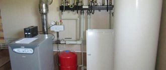
Circulation pump calculation
Selection and calculation of the pump consists of finding out the pressure loss of the coolant flowing throughout the entire pipeline network. The result will be a figure showing how much pressure the circulation pump should develop in order to “push” water through the system. This pressure is calculated using the formula:
P = Rl + Z, where:
- P – pressure loss in the pipeline network, Pa;
- R – specific friction resistance, Pa/m;
- l – pipe length in one section, m;
- Z – pressure loss in local resistances, Pa.
Note. Two-pipe and one-pipe heating systems are calculated in the same way, according to the length of the pipe in all branches, and in the first case, the forward and return lines.
This calculation is quite cumbersome and complex, while the value of Rl for each section can be easily found using the same Shevelev tables. In the example, the blue circle marks the values of 1000i in each section; it only needs to be recalculated along the length of the pipe. Let's take the first section from the example, its length is 5 m. Then the friction resistance will be:
Rl = 26.6 / 1000 x 5 = 0.13 Bar.
We also calculate all sections of the associated heating system, and then summarize the results. It remains to find out the value of Z, the pressure drop in local resistances. For the boiler and radiators, these numbers are indicated in the product passport. For all other resistances, we recommend taking 20% of the total friction losses Rl and summing all these indicators. We multiply the resulting value by a safety factor of 1.3, this will be the required pump pressure.
You should know that pump performance is not the capacity of the heating system, but the total water flow through all branches and risers. An example of its calculation is presented in the previous section, but to select a pumping unit, you also need to provide a reserve of at least 20%.
Results of hydraulic calculations
As a result, it is necessary to sum up the resistance of all sections up to each radiator and compare with the control values. In order for the pump built into the gas boiler to provide heat to all radiators, the pressure loss on the longest branch should not exceed 20,000 Pa. The coolant movement speed in any area should be in the range of 0.25 - 1.5 m/s. At a speed above 1.5 m/s, noise may appear in the pipes, and a minimum speed of 0.25 m/s is recommended according to SNiP 2.04.05-91 to avoid airing of the pipes.
In order to withstand the above conditions, it is enough to select the correct pipe diameters. This can be done using the table.
| Pipe | Minimum power, kW | Maximum power, kW |
| Metal-plastic pipe 16 mm | 2,8 | 4,5 |
| Metal-plastic pipe 20 mm | 5 | 8 |
| Metal-plastic pipe 26 mm | 8 | 13 |
| Metal-plastic pipe 32 mm | 13 | 21 |
| Polypropylene pipe 20 mm | 4 | 7 |
| Polypropylene pipe 25 mm | 6 | 11 |
| Polypropylene pipe 32 mm | 10 | 18 |
| Polypropylene pipe 40 mm | 16 | 28 |
It indicates the total power of the radiators that the pipe provides heat.
Calculation of heat losses
This calculation can be performed independently, since the formula has long been derived. However, calculating heat consumption is quite complex and requires consideration of several parameters at once.
To put it simply, it comes down only to determining the loss of thermal energy, expressed in the power of the heat flow, which is radiated into the external environment by each square meter of the area of the walls, ceilings, floors and roofs of the building.
Related article: How to choose an interesting interior for a room
If we take the average value of such losses, they will be:
- about 100 watts per unit area - for average walls, for example, brick walls of normal thickness, with normal interior decoration, with double-glazed windows installed;
- more than 100 Watts or significantly more than 100 Watts per unit area, if we are talking about walls with insufficient thickness, not insulated;
- about 80 watts per unit area, if we are talking about walls with sufficient thickness, having external and internal thermal insulation, with installed double-glazed windows.
To determine this indicator with greater accuracy, a special formula has been developed in which some variables are tabular data.
Quick selection of pipe diameters from the table
For houses up to 250 sq.m. provided that there is a 6-piece pump and radiator thermal valves, you don’t have to do a full hydraulic calculation. You can select the diameters from the table below. On short sections you can slightly exceed the power. Calculations were made for coolant Δt=10oC and v=0.5m/s.
| Pipe | Radiator power, kW |
| Pipe 14x2 mm | 1.6 |
| Pipe 16x2 mm | 2,4 |
| Pipe 16x2.2 mm | 2,2 |
| Pipe 18x2 mm | 3,23 |
| Pipe 20x2 mm | 4,2 |
| Pipe 20x2.8 mm | 3,4 |
| Pipe 25x3.5 mm | 5,3 |
| Pipe 26x3 mm | 6,6 |
| Pipe 32x3 mm | 11,1 |
| Pipe 32x4.4 mm | 8,9 |
| Pipe 40x5.5 mm | 13,8 |
Accurate calculation of heat losses at home
To quantify the heat loss of a house, there is a special value called heat flow, and it is measured in kcal/hour. This value physically shows the heat consumption that is given off by the walls to the environment under a given thermal regime inside the building.
This value depends directly on the architecture of the building, on the physical properties of the materials of the walls, floor and ceiling, as well as on many other factors that can cause the weathering of warm air, for example, improper installation of the thermal insulation layer.
So, the amount of heat loss of a building is the sum of all heat losses of its individual elements. This value is calculated using the formula: G = S*1/ Po*(Tv-Tn)k, where:
- G is the desired value, expressed in kcal/h;
- Po is the resistance to the process of thermal energy exchange (heat transfer), expressed in kcal/h, this is sq.m*h*temperature;
- Tv, Tn - air temperature indoors and outdoors, respectively;
- k is a reducing coefficient, which is different for each thermal barrier.
It is worth noting that since the calculation is not made every day, and the formula contains temperature indicators that change constantly, it is customary to take such indicators in average form.
This means that average temperature indicators are taken, and for each individual region this indicator will be different.
So, now the formula does not contain unknown terms, which allows for a fairly accurate calculation of the heat losses of a particular house. It remains to find out only the reduction factor and the value of Po - resistance.
Both of these values, depending on each specific case, can be found out from the corresponding reference data.
Some values of the reduction factor:
- floor on the ground or wooden joists - value 1;
- attic floors, in the presence of a roof with roofing material made of steel, tiles on a sparse sheathing, as well as roofing made of asbestos-cement, non-attic roofing with ventilation, - value 0.9;
- the same floors as in the previous paragraph, but arranged on a continuous flooring - value 0.8;
- attic floors, with a roof, the roofing material of which is any rolled material - value 0.75;
- any walls that separate a heated room from an unheated one, which, in turn, has external walls - value 0.7;
- any walls that separate a heated room from an unheated one, which, in turn, does not have external walls - value 0.4;
- floors installed above cellars located below the level of the external ground - value 0.4;
- floors installed above cellars located above the level of the external ground - value 0.75;
- ceilings that are located above basements that are located below the level of the external soil or above by a maximum of 1 m - value 0.6.
Related article: How to properly install an interior door with your own hands (photos and videos)
Based on the cases described above, you can roughly imagine the scale, and for each specific case that is not included in this list, you can independently select a reduction factor.
Some values for heat transfer resistance:
The resistance value for solid brickwork is 0.38.
- for ordinary solid brickwork (wall thickness approximately 135 mm) the value is 0.38;
- the same, but with a masonry thickness of 265 mm - 0.57, 395 mm - 0.76, 525 mm - 0.94, 655 mm - 1.13;
- for solid masonry with an air gap, with a thickness of 435 mm - 0.9, 565 mm - 1.09, 655 mm - 1.28;
- for solid masonry of decorative bricks for a thickness of 395 mm - 0.89, 525 mm - 1.2, 655 mm - 1.4;
- for continuous masonry with a thermal insulation layer for a thickness of 395 mm - 1.03, 525 mm - 1.49;
- for wooden walls made of individual wooden elements (not timber) for a thickness of 20 cm - 1.33, 22 cm - 1.45, 24 cm - 1.56;
- for walls made of timber with a thickness of 15 cm - 1.18, 18 cm - 1.28, 20 cm - 1.32;
- for an attic floor made of reinforced concrete slabs with insulation when their thickness is 10 cm - 0.69, 15 cm - 0.89.
Having such tabular data, you can begin to perform an accurate calculation.
Summarizing
So, calculating the coolant in the heating system shows how much water is required by the entire heating system to maintain the house at normal temperature. The same figure is conditionally equal to the power of the pump, which, in fact, will deliver the coolant to the radiators, where it will release part of its thermal energy into the room.
It is worth noting that the average power of the pumps is approximately 10 cubic meters per hour, which gives a small margin, since the thermal balance must not only be maintained, but sometimes, at the owner’s request, the air temperature must be increased, which, in fact, requires additional power .
Experienced experts recommend purchasing a pump that is approximately 1.3 times more powerful than required. Speaking about a gas heating boiler, which, as a rule, is already equipped with such a pump, you should pay attention to this parameter.
Converting the result to normal form
It is worth noting that in practice you will not find such water consumption anywhere. All water pump manufacturers express pump power in cubic meters per hour.
Some transformations should be made, recalling the school physics course. So, 1 kg of water, that is, coolant, is 1 cubic meter. dm of water. To find out how much one cubic meter of coolant weighs, you need to find out how many cubic decimeters there are in one cubic meter.
Using some simple calculations or simply using tabular data, we find that one cubic meter contains 1000 cubic decimeters. This means that one cubic meter of coolant will have a mass of 1000 kg.
Then in one second it is necessary to pump water with a volume of 2.4/1000 = 0.0024 cubic meters. m.
Now all that remains is to convert the seconds to hours. Knowing that there are 3600 seconds in one hour, we find that in one hour the pump must pump 0.0024*3600 = 8.64 cubic meters per hour.