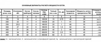
Calculation of air heating efficiency
Installation of a heating system is impossible without preliminary calculations.
The information obtained must be as accurate as possible, so air heating calculations are carried out by experts using specialized programs, taking into account the nuances of the design. You can calculate the air heating system (hereinafter referred to as the air heating system) yourself, having basic knowledge of mathematics and physics.
In this material we will tell you how to calculate the level of heat loss at home and the heat loss system. To make everything as clear as possible, specific examples of calculations will be given.
Calculation of the air heating system of a private house. Heat loss calculation
As a matter of fact, for small private or country houses it is not necessary to accurately calculate heat loss. It is enough to know the heat loss balance of the entire house. Moreover, even an error in calculations of ten percent will not be fatal at all, since the Antares Comfort air heating system has a sufficient reserve of pumped air volumes; it is enough to simply adjust the fan to higher speeds. But you need to understand that, generally speaking, the air flow speed at the exit from the air duct, or rather from the ventilation grille, should not be higher than 1.5 m/s (optimal value), or, in extreme cases, higher than 2 m/s (maximum recommended meaning). Otherwise, vibrations or turbulence may occur, and therefore increased noise levels. Naturally, the power of an electric heater or heating boiler should be enough to compensate for all the real heat losses of the entire house.
When calculating an air heating system for heat loss, it is necessary first of all to calculate the heat loss of all walls. In this case, we can roughly assume that 5 cm of mineral wool has the same heat loss as 15 cm of timber or logs, 30 cm of foam blocks or 50 cm of brick. We are talking, of course, about the thickness of the wall made of the mentioned materials. Those. for example, a wall with 5 cm of URSA mineral wool insulation will have the same heat loss as a wall made of timber 15 cm thick or a brick wall 50 cm thick.
When calculating, we can assume that for a wall made of 5 cm of mineral wool slab, the heat loss will be approximately 48 W/m2, for a wall of 10 cm - 25 W/m2, for a wall of 15 cm - 16 W/m2. Usually no one installs more than three layers of insulation (5 cm x 3 layers = 15 cm). These figures also include heat loss from the frame of the house in which the insulation is located.
But what if the walls of your house consist of different materials, for example, the wall itself is made of 150 x 150 timber, and there is another layer of insulation installed on the outside? In this case, it is easier to reduce everything to one type of material - mineral wool. As mentioned above, 15 cm of timber is equivalent to 5 cm of mineral wool, so we will assume that the heat loss of our composite wall is equivalent to the heat loss of a wall made of 10 cm of mineral wool (15 cm of timber is 5 cm of mineral wool, plus another layer of 5 cm of mineral wool = 10 cm) - those. 25 W/m2
The heat loss of the lower floor and roof is calculated in exactly the same way as the heat loss of the walls, but the resulting result must be increased by 30% - since wooden frame elements are located more often in the floors and roof than in the walls. For example, for a roof made of 15 cm of mineral wool insulation, the heat loss will not be 16 W/m2, but 24 W/m2
There is another, easier way to determine the equivalent thickness of mineral wool insulation for calculating heat loss - a calculator for calculating the heating of a private house, made in the form of a Microsoft Excel file. On the second sheet of the calculator you can put the thickness of all materials used in the wall, roof or ceiling and get the thermal equivalent of a polystyrene foam wall. In this case, heat loss q per square meter of such a wall is determined by the formula:
where Tnorm is the normalized winter temperature of the region in which the house is built, for example, for the Moscow region it is -28°C.
For a frame structure (for example a roof or ceiling), the thermal equivalent value must be reduced by 10%.
Calculating the heat loss of windows and doors is also not difficult. For an ordinary wooden window from the era of developed socialism (the one with slots for ventilation) this is 200 W/m2. For double-glazed windows - 100 W/m2. For more expensive and modern double-glazed windows - 80 W/m2. The heat loss of external doors can be approximately taken as 90 W/m2.
In addition to direct heat loss (through walls, ceilings and roof), in any house there is also heat loss due to ventilation. But it is easier to take them into account not through the heat consumption itself (in W), but through the air volumes necessary to compensate for them. Therefore, we will take them into account later, at stage 2.
The calculation of heat loss given here is approximate. But it nevertheless allows you to obtain a balance of heat loss throughout the house. Cardinal directions, wind rose, heating by solar radiation through windows, etc. are not taken into account in this calculation, but for small private houses they are not needed. Moreover, we will increase the figures obtained in the calculations by 2 times for reliability, thus obtaining a significant margin of the required power of the heater or heating boiler. And the power of the fan of the Antares Comfort air heating system is certainly enough to pump the required volume of air, if necessary.
For cold floors on the first or basement floors, the resulting heat loss must be increased by 10%. This, firstly, will allow for possible calculation errors to be taken into account, and secondly, it will more accurately equalize the temperature on the first and second floors, because Warm air from the first floor will always rise to the second.
After the specific heat loss values have been calculated for each element of the surface of the house (walls, roof, floor, ceilings, windows, doors), it is necessary to determine the area of each of these elements in contact with the environment and calculate the total heat loss. In this case, the area is determined by the outer contour of the walls. To calculate the area of the walls of the second floor, the height of the walls of the gables is taken up to the roof, if the second floor is heated and the roof and gables are fully insulated.
Total heat loss Q through each surface element of a house is the product of its area S and its specific heat loss q:
The house we are considering as an example has walls built from sip panels, i.e. 1.2 cm OSB + 14 cm polystyrene foam + 1.2 cm OSB, specific heat loss q = 17 W/m2
Floors and roofs are similar - 1.2 cm OSB + 18 cm polystyrene foam + 1.2 cm OSB, specific heat loss q = 17 W/m2
For windows, the owner of the house wanted to have double-glazed windows, specific heat loss q = 100 W/m2
Having calculated all the heat losses and tabulated them, we get the following result:
| 1st floor | Heat loss, W | Attic | Heat loss, W |
| 1.1. | 467 | 2.1. | 1 294 |
| 1.2. | 747 | 2.2. | 760 |
| 1.3. | 74 | 2.3. | 1 126 |
| 1.4. | 133 | 2.4. | 801 |
| 1.5. | 921 | Total | 3 981 |
| 1.6. | 2 210 | ||
| Total | 4 553 | Total | 8 534 |
Let's move on to stage 2.
Calculator of the required power of an air heating unit
Air heating of residential buildings is not as widespread as “classic” water heating, but, nevertheless, interest in it among potential owners still tends to grow - it has proven its efficiency and cost-effectiveness. The principle of such space heating itself consists in heating the air flow with special equipment, which is then directed into the room or a certain area with the help of fans.
Calculator of the required power of an air heating unit
By the way, the simplest and most common (albeit somewhat simplified) type of air heating is the installation of stationary or portable fan heaters in the room. More advanced systems that serve the whole house include, in addition to the heating unit, an extensive air duct system, automatic monitoring and control, air purification and disinfection devices. Often such heating systems are combined with forced ventilation, and this also imposes certain requirements on its organization.
Prices for air heating units
Be that as it may, the “heart” of such a heating system, regardless of its degree of complexity, is the air-heating unit. And its operational parameters must correspond to the conditions in which it will be operated - the built-in power potential must be sufficient to heat a specific room or the entire house as a whole. How to decide on this? – let’s call for help with a calculator of the required power of the air heating unit.
Some explanations on the use of the program will be given below.
Calculator of the required power of an air heating unit
Explanations for calculations
When calculating any heat generator, it is based on the consideration that the energy it generates should be enough to fully compensate for heat losses from a specific room and then (if we are talking about the heating system of the entire house) from the building as a whole. In this case, of course, a certain operational power reserve is also provided.
Using the widely accepted “postulate” that 100 W of thermal energy is required per 1 m² of area - this path will not give an accurate result. Heat losses that require compensation through the operation of the heating system depend not only, and not even so much, on the area of the premises, but on a number of other diverse factors. All this is implemented in the proposed calculator.
Important – the calculation is carried out for each room separately. If local heating of the room is planned, then the obtained value will be sufficient. In the same case, when the entire heating system for a house is calculated, after calculating the rooms connected to the system, all the obtained indicators are summed up. It is best to avoid mistakes by making a sign in advance where all the rooms are listed, listing their specific features, and then sit down to do the calculations.
So, how is the calculation carried out for a specific room:
- The volume of the room is of course important, and for this it is necessary to indicate the area and height of the flow.
- The number of walls bordering the street matters. It is clear that the more there are, the higher the possible heat losses.
- It makes sense to pay attention to the location of the outer wall of the room relative to the cardinal directions. On the south side, the room receives an additional “thermal charge” from the Sun, but on the opposite side the walls are completely deprived of this opportunity, and will cool down faster.
- If there is such information, then you can indicate the position of the external wall relative to the prevailing wind direction in the winter season - the program will make the appropriate amendment. If such data is not available, the calculator will make calculations for the most unfavorable conditions.
- The amendment not to the climatic features of the region will be taken into account by the following point. It is necessary to indicate the minimum temperatures in the coldest ten days of winter - but not abnormal ones , but those considered normal for your area.
- The next input field is the state of the thermal insulation of the walls. They can be considered fully insulated only if this was carried out on the basis of thermal engineering calculations. It is clear that there should be no completely uninsulated walls in a residential building at all - otherwise there is no point in setting up a heating system.
- A very impressive share of heat loss occurs on floors and ceilings (ceilings). In order not to miss this moment, in the following input fields you must select the option of “neighborhood” of the room being calculated vertically - above and below.
- Next, several input fields are dedicated to windows - their type, quantity, size. Based on the information received, the calculation program will enter the necessary correction factor for glazing.
- The room may have a door to the outside (or to an unheated area) that will let in a considerable amount of cold air each time it is opened. This requires appropriate compensation from the heating system.
For a closed air heating system, you can go to the “CALCULATE” button and get the result expressed in watts and kilowatts (it already takes into account the 15 percent operating reserve).
But often the air heating system is combined with fresh air ventilation - and then the heating unit is required not only to replenish heat loss, but also to ensure heating of the air flow constantly coming from the street. This also needs to be taken into account in the calculations. If you select this path, additional data entry fields will appear.
- It is necessary to clarify the ceiling height to accurately determine the volume of air exchange.
- Supply ventilation can be turned off in severe frosts - it is necessary to indicate the lower temperature limit for its operation. This will allow you to determine the maximum temperature range (taking into account maintaining a comfortable level of +20 °C in the room).
- And finally, it is necessary to indicate the expected rate of complete air exchange in the room. Usually, calculations are based on a one-time rate, but just in case, the functionality of the calculator has been expanded - from 0.5 to 2 volumes per hour.
After this, all that remains is to press the “CALCULATE” button to get the result.
Are you thinking about air heating your home? Then this is the place for you...
Many owners of country houses do not even really know about the existence of air heating systems. To fill this information gap, we recommend following the link to the article on our portal dedicated to the review of air heating units .
Sequence of actions when installing air heating
To install an air heating system for a workshop and other production premises, you must adhere to the following sequence of actions:
- Development of a design solution.
- Heating system installation.
- Carrying out commissioning and testing of air and automation systems.
- Acceptance for operation.
- Exploitation.
Below we will consider each stage in more detail.
Air heating system design
The correct location of heat sources around the perimeter will allow the rooms to be heated in the same volume. Click to enlarge.
Air heating of a workshop or warehouse must be installed in strict accordance with a previously developed design solution.
You should not carry out all the necessary calculations and select equipment yourself, since errors in design and installation can lead to malfunctions and the appearance of various defects: increased noise levels, imbalance of air supply to rooms, temperature imbalance.
The development of a design solution should be entrusted to a specialized organization, which, based on the technical conditions (or technical specifications) submitted by the customer, will solve the following technical problems and issues:
- Determination of heat losses in each room.
- Determination and selection of an air heater of the required power, taking into account the amount of heat loss.
- Calculation of the amount of heated air taking into account the power of the air heater.
- Aerodynamic calculation of the system, performed to determine the pressure loss and diameter of the air channels.
After completing the design work, you should begin purchasing equipment, taking into account its functionality, quality, range of operating parameters and cost.
Installation of an air heating system
Work on installing a workshop air heating system can be done independently (by specialists and company employees) or you can resort to the services of a specialized organization.
When installing the system yourself, it is necessary to take into account some specific features.
Before starting installation, it would be a good idea to make sure that the necessary equipment and materials are complete.
Air heating system layout diagram. Click to enlarge.
At specialized enterprises producing ventilation equipment, you can order air ducts, tie-ins, butterfly valves and other standard products used in the installation of air heating systems for industrial premises.
Additionally, you will need the following materials: self-tapping screws, aluminum tape, mounting tape, flexible insulated air ducts with a noise-attenuating function.
When installing air heating, it is necessary to provide insulation (thermal insulation) of the supply air ducts.
This measure is intended to eliminate the possibility of condensation formation. When installing main air ducts, galvanized steel is used, on top of which foil self-adhesive insulation with a thickness of 3 mm to 5 mm is glued.
The choice of rigid or flexible air ducts or their combination depends on the type of air heater determined by the design solution. The air ducts are connected to each other using reinforced aluminum tape, metal or plastic clamps.
The general principle of installing air heating boils down to the following sequence of actions:
- Carrying out general construction preparatory work.
- Installation of the main air duct.
- Installation of exhaust air ducts (distribution).
- Air heater installation.
- Thermal insulation device for supply air ducts.
- Installation of additional equipment (if necessary) and individual elements: heat exchangers, grilles, etc.
Calculation of ventilation: exhaust and supply
According to the method of operation, ventilation circuits can be divided into three groups: exhaust (removing used air), supply (introducing clean air into the room), and (recuperation combining functions of the first and second categories).
In any case, when calculating ventilation, many factors must be taken into account - these are:
- pressure in air channels;
- air flow;
- heater power;
- cross-sectional area of ventilation ducts.
PRESSURE AND SECTION
The pressure and, accordingly, the speed of movement of air masses is affected by the cross-sectional area of the channels, as well as their configuration, the power of the electric fan and the number of transitions.
When calculating the diameter of the channels, the following values are empirically taken:
- For residential premises – 5.5 sq.cm. per 1 sq.m. area.
- For a garage and other industrial premises - 17.5 sq.cm. per 1 sq.m.
In this case, a flow speed of 2.4 – 4.2 m/sec is achieved.
Pros and cons of air heating
– Versatility: you get heating, ventilation, air conditioning, air purification “in one bottle” - a full-fledged climate system, and not just heating the air in the premises of the house
– Lightness, speed, design: control is carried out automatically using the latest “smart” thermostats in the form of newfangled electronic programmable gadgets; the heating rate is ensured by the absence of intermediate links (coolant in pipes and heating radiators) - air of the required temperature immediately enters the premises.
– Highest system efficiency, reaching 95% with condensing gas air heaters. Operational logistics and operational temperature control can significantly reduce overall energy consumption and save money. By comparison, traditional water heating systems have an energy efficiency of no more than 60%.
– Highest reliability with gas heating. The absence of coolant liquid eliminates leaks, air pockets and defrosting.
– Ease of maintenance. It is enough to clean or change the air filter in a timely manner.
Disadvantages of air heating:
– air heating is suitable for houses with an area of over 90 sq.m. – if the area is smaller, installation is impractical
– the installation of the air system is carried out before the final interior finishing, so the best option is its design and installation during the construction stage of the house
– air ducts occupy a certain space, which may entail (but not necessarily) reducing the height in the places where they are located to a maximum of 20 cm.
– correct implementation of the system requires professional calculations and project development. Although air duct assembly can be done with your own hands, without the help of specialists, it requires certain tools.
Air exchange calculation
Experts use two main schemes:
- According to aggregated indicators. This technique does not involve harmful emissions such as heat and water. Let's call it “Method No. 1”.
- Method taking into account excess heat and moisture. Conventional name “Method No. 2”.
Method No. 1
The unit of measurement is m 3 / h (cubic meters per hour).
Two simplified formulas are used: L=K ×V(m 3 /h); L=Z ×n (m 3 / h), where
K – air exchange rate. The ratio of the air supply volume in one hour to the total air in the room, times per hour; V – volume of the room, m3; Z is the value of specific air exchange per unit of rotation, n is the number of units of measurement.
The selection of ventilation grilles is carried out according to a special table. The selection also takes into account the average speed of air flow through the channel.
Selection table for ventilation grill sizes
Method No. 2
The calculation takes into account the assimilation of heat and moisture. If there is excess heat in an industrial or public building, then the formula is used:
where ΣQ is the sum of heat releases from all sources, W; с – thermal capacity of air, 1 kJ/(kg*K); tyx – temperature of air directed to the exhaust, °C; tnp—temperature of air directed to the inlet, °C; Exhaust air temperature:
where tp.3 is the standard temperature in the work area, 0 C; ψ - temperature increase coefficient, depending on the measurement height, equal to 0.5-1.5 0 C/m; H – arm length from the floor to the middle of the hood, m.
When the technological process involves the release of a large volume of moisture, a different formula is used:
where G is the volume of moisture, kg/h; dyx and dnp – water content per kilogram of dry supply and exhaust air.
There are several cases, described in more detail in the regulatory documentation, when the required air exchange is determined by the multiplicity:
k – frequency of indoor air changes, once per hour; V is the volume of the room, m3.
Section calculation
The cross-sectional area of the duct is measured in m2. It can be calculated using the formula:
where v is the speed of air masses inside the channel, m/s.
It varies for main air ducts 6-12 m/s and side appendages no more than 8 m/s. Quadrature affects the channel capacity, the load on it, as well as the noise level and installation method.
Calculation of pressure loss
The walls of the air duct are not smooth, and the internal cavity is not filled with vacuum, so part of the energy of the air masses during movement is lost to overcome these resistances. The amount of loss is calculated using the formula:
where ג is friction resistance, defined as:
The formulas given above are correct for channels with a circular cross-section. If the duct is square or rectangular, then there is a formula for converting to an equivalent diameter:
where a,b are the dimensions of the channel sides, m.
Pressure and engine power
The air pressure from the blades H must completely compensate for the pressure loss P, while creating the calculated dynamic Pd at the outlet.
Electric fan motor power:
Selection of heater
Often heating is integrated into the ventilation system. For this purpose, air heaters, different types of recuperators, as well as the recirculation method are used. The choice of device is carried out according to two parameters:
- Qв – maximum consumption of thermal energy, W/h;
- Fk – determination of the heating surface for the heater.
Calculation of gravitational pressure
Can only be used for natural ventilation systems. With its help, its performance is determined without mechanical stimulation.
Examples of air exchange volume calculations
The following is an example of calculating ventilation based on the exchange rate. For this purpose, we will consider a private house with the following premises:
- kitchen - 19 sq. m;
- living room - 41 sq. m;
- bathroom - 3 sq. m;
- children's room - 14 sq.m. m;
- office - 17 sq. m;
- bedroom - 22 sq. m;
- bathroom - 4 sq. m;
- corridor - 6 sq. m.
The ceiling height in the house is 3 m. To calculate, you need to determine the volume of each room. In this case we get the following values:
- kitchen - 57 cubic meters m;
- living room - 123 cubic meters m;
- bathroom - 9 cubic meters. m;
- children's room - 42 cubic meters. m;
- cabinet - 51 cubic meters m;
- bedroom - 66 cu. m;
- bathroom - 12 cubic meters m;
- corridor - 18 cubic meters m.
air exchange diagram
Using the table of multiplicity values from the regulatory document, a calculation is carried out in accordance with the above formula:
- kitchen - 57 = 57 (19 sq. m x 3) - rounded to 60;
- living room - 3 x 123 - rounded to 370;
- bathroom - 9 = 9 (3 sq. m x 3) - rounded to 10;
- children's room - 1 x 42 - rounded to 45;
- office - 1 x 51 - rounded to 55;
- bedroom - 1 x 66 - rounded to 70;
- bathroom - 12 = 12 (4 sq. m x 3) - rounded to 15;
- corridor - 18 = 18 (6 sq. m x 3) - rounded to 20;
Here, during the calculations, it was taken into account that the regulatory document does not contain multiplicities for the bathroom, corridor, toilet and kitchen. In this case, the area of the corresponding premises was multiplied by 3. After this, the final value was rounded up to a multiple of 5.
Now they are summing up the rooms into which clean air initially flows - this is the living room, office, bedroom, children's room. After summation, you will get 370 + 55 + 70 + 45 = 540 cubic meters. m. So much air should enter the house through the use of a ventilation system.
Now you need to sum up the values for those rooms where there is exhaust ventilation. We are talking about the corridor, kitchen, bathroom and toilet. The result will be 20 + 60 + 15 + 10 = 105 cubic meters. m. According to calculations, this amount of air should be discharged outside.
Initial data for thermal calculation of the heating system
Before you start calculating and working with data, you need to obtain it
Here, for those owners of country houses who have not previously been involved in design activities, the first problem arises - what characteristics are worth paying attention to. For your convenience, they are summarized in a small list below.
- Building area, ceiling height and internal volume.
- Type of building, presence of adjacent buildings.
- Materials used in the construction of the building - what and how the floor, walls and roof are made of.
- The number of windows and doors, how they are equipped, how well they are insulated.
- For what purposes will these or those parts of the building be used - where the kitchen, bathroom, living room, bedrooms will be located, and where - non-residential and technical premises.
- Duration of the heating season, average minimum temperature during this period.
- “Wind rose”, the presence of other buildings nearby.
- An area where a house has already been built or is about to be built.
- Preferred temperature for residents in certain rooms.
- Location of points for connecting to water supply, gas and electricity.
Heat loss in the house
Thermal insulation measures shown in the image above will help to significantly reduce the amount of energy and coolant required to heat a residential building
Air heater power calculation
Calculation of air heater power.
To calculate the heater power P (W) required to heat the supply air of the required volume, the general formula P = Q × 0.36 × (t in.t out) is used, where:
Q – air flow (m 3 / h);
t in. (°C) – outside air temperature;
tout (°C) – room air temperature.
The temperature to which the air heater can heat the air can be determined using the formula:
For example, with a heater power of 1.5 kW and an air flow rate pumped by a fan of 100 m 3 / h, the selected device will heat the air by Δt = 2.98 × 1500/100 = 44.7 ° C. This means that with a minimum value of incoming air of -20°C, the temperature at the outlet of the air heater will be 45-20=25°C. For a heater installed in apartments, the power is taken from 1 to 5 kW. In large houses, offices and other similar buildings, air heaters can have a power of 5 to 50 kW.
Ventilation calculation table.
To heat the forced air, duct heaters are installed. The devices are mounted directly into air ducts of both round and rectangular cross-sections. If it is impossible to provide power supply to air heaters with the performance obtained as a result of the calculation, devices with coolant from autonomous heating are used as heat exchangers.
This option for heating the supply air is more suitable for country houses. Antifreeze liquid is added to the coolant of the device, and the device is equipped with automatic means of protection against freezing. Based on the technical characteristics of air heaters and the required performance, their number is determined. The number of heat exchangers to reduce heat costs for ventilation should be minimal.
Calculation of the air heating system of a private house. Calculation of the amount of warm air.
We assume that each cubic meter of air can transfer 10 W of heat. Then we get the following results of air flow (per hour) for each room of the house:
| 1st floor | Air volume | Attic | Air volume |
| 1.1. | 47 | 2.1. | 65 |
| 1.2. | 74 | 2.2. | 76 |
| 1.3. | 73 | 2.3. | 113 |
| 1.4. | 13 | 2.4. | 80 |
| 1.5. | 92 | Total | 334 |
| 1.6. | 226 | ||
| Total | 525 | Total | 859 |
Now let's return to taking into account heat loss for ventilation, remember we talked about this at stage 1?
Heat loss due to ventilation is taken into account simply. For each person you need 30 m³/hour of fresh air, for each heating boiler - 2 m³/hour per 1 kW of boiler power, for each gas stove - 15 m³/hour.
As already mentioned at the beginning of the article, 3 people live in the house, there is a gas stove and a heating boiler of 18 kW. Those. ventilation requires an additional 140 m³/hour of air:
If all this is translated into heat loss, then for the Moscow region (in which our house is built) at a normalized winter temperature of 28°C, to warm the air to room temperature, you will need to spend 23 W per cubic meter, a total of 3.2 kW for additional heat loss. ventilation.
Now you need to carefully analyze the resulting table with air flow. For example, in this house, heat loss in the corridor on the first floor is minimal, but in the corridor on the second floor, on the contrary, it is quite large. Therefore, it would be advisable to make a slight redistribution of flows - supply part of the air for the second floor corridor on the contrary to the corridor on the first floor - warm air will still reach the second floor naturally.
Ventilation calculation
Ventilation serves to maintain a sufficient amount of fresh, clean air in the room and to remove exhaust polluted air from the room. In addition, ventilation ensures air movement in the room, which helps eliminate excess moisture, dampness, stagnant air and accumulated odors. In order to select all the necessary components, it is necessary to calculate the ventilation system.
Calculation of supply ventilation
Supply ventilation calculations are performed for each room separately. The calculation algorithm depends on the purpose of the room. So, for office premises, foyers and meeting rooms, different dependencies will be applied.
First of all, when calculating the supply ventilation, you should refer to the regulatory documents - codes of practice (SP) for the type of object in question:
- SP 44.13330.2011 - Administrative and domestic buildings
- SP 54.13330.2016 – Residential multi-apartment buildings
- SP 56.13330.2011 – Industrial buildings
- SP 57.13330.2011 – Warehouse buildings
- SP 113.13330.2016 – Car parking
- SP 118.13330.2012* - Public buildings and structures
- SP 278.1325800.2016 – Buildings of educational institutions of higher education
The codes of practice provide tables of air exchange rates for various rooms. For example, according to clause 7.31 of SP 118.13330.2012, the air exchange rate in a store must be at least 1. Let us recall that the air exchange rate shows how many times the air in the room should be changed in one hour. Therefore, in order to calculate the supply ventilation, it is necessary to determine the volume of the store premises.
Let's assume the store area is 50 m2, the ceiling height is 3 meters. Then the volume of the room will be 150 m 3, and the required supply air flow will be 150·1=150 m 3 /h.
For other types of objects, the standards may indicate not the air exchange rate, but the air flow per person. Thus, according to Table 7.3 SP 118.13330.2012 in cinema auditoriums, the air flow per viewer must be at least 20 m 3 /h. In this case, the calculation of supply ventilation will consist of counting the number of spectators and multiplying the resulting value by 20 m 3 / h. For an auditorium with a capacity of 300 people we get: 300·20 = 6000 m 3 /h.
Calculation of exhaust ventilation
The calculation of exhaust ventilation is also carried out taking into account the requirements of the codes of practice, the list of which is given above. For example, a single air exchange in a store will mean that the performance of the exhaust system should also be 1 room volume per hour (150 m 3 /h for the store in question).
However, there is one peculiarity when calculating exhaust ventilation. In “clean” rooms (offices, classrooms, meeting rooms, living rooms and other premises with permanent human occupation), it is recommended that the exhaust air flow rate be less than the supply air flow rate. This is done so that the “excess” air goes into adjacent rooms - into corridors and technical rooms. This ensures protection against the flow of odors from adjacent rooms and residential and office areas.
In addition, at any facility there are rooms where only exhaust is provided - bathrooms, showers, technical rooms, wardrobes and others. As a rule, standards require that separate exhaust systems be installed for them. In this case, the calculation of exhaust systems is based on the following figures:
- Exhaust air from one toilet: 50 m 3 /h
- Hood from one sink: 25 m 3 /h
- Exhaust air from one shower stall: 75 m 3 /h
- Exhaust from technical rooms: 1 times.
Calculation of supply and exhaust ventilation
The calculation of supply and exhaust ventilation comes down to calculating the supply and exhaust ventilation systems separately. Further, the function of two systems can be performed by one unit - an air handling unit.
Supply and exhaust units are usually used for general ventilation systems. Taking into account the predominance of supply air over exhaust, which was mentioned above, in such installations the flow of supply air is greater than that of exhaust air. In addition, the aerodynamic resistance of the supply system is always higher than the exhaust system due to the presence of filtration, heating, and sometimes cooling sections. Therefore, exhaust fans are usually provided with lower power than supply fans.
Finally, when calculating supply and exhaust ventilation, you can save money by providing a heat recuperator. This is a device that transfers heat from the exhaust air to the supply air. In winter, the recuperator is able to warm up the supply air quite strongly at the expense of the exhaust air and, as a result, significantly reduce the heater power.
Heat consumption for ventilation
According to its purpose, ventilation is divided into general, local supply and local exhaust.
General ventilation of industrial premises is carried out by supplying fresh air, which absorbs harmful emissions in the work area, acquiring its temperature and humidity, and is removed using an exhaust system.
Local supply ventilation is used directly at workplaces or in small rooms.
Local exhaust ventilation (local suction) must be provided when designing process equipment to prevent air pollution in the working area.
In addition to ventilation, air conditioning is used in industrial premises, the purpose of which is to maintain a constant temperature and humidity (in accordance with sanitary, hygienic and technological requirements) regardless of changes in external atmospheric conditions.
Ventilation and air conditioning systems are characterized by a number of general indicators (Table 22).
Heat consumption for ventilation, to a much greater extent than heat consumption for heating, depends on the type of technological process and production intensity and is determined in accordance with current building codes and regulations and sanitary standards.
The hourly heat consumption for ventilation QI (MJ/h) is determined either by the specific ventilation thermal characteristics of buildings (for auxiliary premises) or by production
At light industry enterprises, various types of ventilation devices are used, including general exchange ones, for local suction, air conditioning systems, etc.
The specific ventilation thermal characteristic depends on the purpose of the premises and is 0.42 - 0.84 • 10~3 MJ/(m3 • h • K).
Based on the productivity of the supply ventilation, the hourly heat consumption for ventilation is determined by the formula
duration of existing supply ventilation units (for industrial premises).
Based on specific characteristics, hourly heat consumption is determined as follows:
In the event that the ventilation unit is intended to compensate for air losses during local suction, when determining QI, they take into account not the outside air temperature for calculating ventilation tHb, but the outside air temperature for calculating heating /n.
In air conditioning systems, heat consumption is calculated depending on the air supply pattern.
Thus, the annual heat consumption in direct-flow air conditioners operating using outside air is determined by the formula
If the air conditioner operates with air recirculation, then in the formula, by definition, Q£con instead of the supply temperature
The annual heat consumption for ventilation QI (MJ/year) is calculated using the equation
Arguments for choosing an air system
Air heating has a wide range of advantages and some disadvantages. Pros:
- High efficiency. The performance of the circuit when heated with air reaches 94%.
- Putting equipment into operation at any time of the year. You don’t have to worry about the pipelines defrosting or breaking – there’s nothing there to freeze, so there won’t be any accidents when the pipeline is turned off and then turned on again in the winter.
- Reduced operating costs. There is no need to buy expensive equipment, shut-off valves, etc.
- You can connect a heating and cooling system, providing a comfortable temperature throughout the year.
- Reduced inertia of the circuit, which guarantees quick heating of rooms.
- You can install any additional equipment to maintain a comfortable microclimate - humidifiers, ionizers, sterilizers.
- Versatility. The system is used for premises of any size, buildings of different heights.
- Uniform heating. There will be no local hot spots.
Disadvantages of air heating:
- energy dependence - the electricity will be turned off, the fan will stop working, the air will not flow through the pipelines;
- the need for regular monitoring and maintenance of the circuit;
- installation of the structure is carried out during the construction phase; the system does not change and cannot be modernized during its entire service life.
Classification of air heating systems
Such heating systems are divided according to the following characteristics:
By type of energy carrier: systems with steam, water, gas or electric heaters.
According to the nature of the supply of heated coolant: mechanical (using fans or blowers) and natural impulse.
According to the type of ventilation schemes in heated rooms: direct-flow, or with partial or complete recirculation.
By determining the place of heating of the coolant: local (the air mass is heated by local heating units) and central (heating is carried out in a common centralized unit and is subsequently transported to heated buildings and premises).