Schematic illustration
The functionality of a four-way valve is based on the rotation of a spindle installed inside it. Its movement is not limited since there is no thread on the bushing. There are 2 selections on the working part of the moving element. Water flows through them through two channels. This leads to the fact that liquid cannot enter all channels at the same time and is distributed evenly.
Schematic representation of the valve operating mode Source domotopim.ru
Healthy! The moving coolant enters one of two pipes located on the right or left side of it. This principle is used to mix water throughout the entire system.
There are models of four-way valves without a spindle. Instead, a pressure rod is installed. The disadvantage of this design is the lack of a stream mixing function.
The operation of the four-way valve is controlled in 2 ways:
- Manual. To distribute the liquid, the rod is installed strictly in one position. Setting modes is also done manually.
- Automatic. The rotating element begins to move after receiving a command transmitted by a sensor installed outside. The specific design ensures that a constant set temperature is maintained.
A four-way valve for heating is used to reduce the excessive consumption of the coolant used. The simple design of the device allows the element to be operated without differential bypasses, due to the valve’s ability to pass only a certain volume of liquid through itself.
The device is indispensable where constant monitoring of the coolant temperature is necessary. First of all, these include radiator-type heating systems with a boiler powered by solid fuel (wood, coal).
In cases with other heating systems, the temperature of the coolant is regulated thanks to a water pump and bypass; here these functions are assigned to a four-way valve. As a result, the operation of the boiler is stable, and the amount of coolant received does not exceed the norm.
Heating with four-way valve
Installation of a heating system with a four-way valve:
The connection diagram for a heating system with a four-way mixer consists of the following elements:
- Boiler;
- Four-way thermostatic mixer;
- Safety valve;
- Pressure reducing valve;
- Filter;
- Ball valve;
- Pump;
- Heating batteries.
The installed heating system must be flushed with water. This is necessary so that various mechanical particles are removed from it. After this, the operation of the boiler must be checked under a pressure of 2 bar and with the expansion tank turned off.
Please note that a short period of time must pass between the start of full operation of the boiler and its testing under hydraulic pressure. The time limit is due to the fact that if there is no water in the heating system for a long time, it will be susceptible to corrosion.
A four-way valve is an element of the heating system to which four pipes having coolants of different temperatures are connected, and is used to prevent overheating of a solid fuel boiler. The thermostatic valve prevents the temperature inside the boiler from exceeding 110 °C. Already at a temperature of 95 °C it starts cold water to cool the system.
Four way valve design
The body is made of brass, 4 connecting pipes are attached to it. Inside the body there is a sleeve and a spindle, the operation of which has a complex configuration.
The thermostatic mixing valve performs the following functions:
- Mixing water flows of different temperatures. Thanks to mixing, there is a smooth regulation of water heating;
- Boiler protection. The four-way mixer prevents corrosion, thereby extending the life of the equipment.
Four-way mixer diagram
The operating principle of such a heating valve is to rotate the spindle inside the housing. Moreover, this rotation must be free, since the sleeve does not have a thread. The working part of the spindle has two openings through which the flow opens in two passes. Thus, the flow will be throttled and will not be able to pass directly to the second sample. The flow will be able to turn into any of the nozzles located on the left or right side of it. So, all flows coming from opposite sides are mixed and distributed over four pipes.
There are designs in which a pressure rod works instead of a spindle, but such devices cannot mix flows.
Valve operation is controlled in two ways:
- Manual. Flow distribution requires the rod to be installed in one specific position. This position must be adjusted manually.
- Auto. The spindle rotates as a result of a command received from an external sensor. Thus, the heating system constantly maintains the set temperature.
The four-way mixing valve ensures a stable flow of cold and hot coolant. The principle of its operation does not require the installation of a differential bypass, because the valve itself allows the required amount of water to pass through. The device is used where temperature control is necessary. First of all, this is a radiator heating system with a solid fuel boiler. If in other cases the coolant is regulated using a hydraulic pump and bypass, here the operation of the valve completely replaces these two elements. As a result, the boiler operates in a stable mode, constantly receiving a dosed amount of coolant.
Heating with four-way valve
Installation of a heating system with a four-way valve:
The connection diagram for a heating system with a four-way mixer consists of the following elements:
- Boiler;
- Four-way thermostatic mixer;
- Safety valve;
- Pressure reducing valve;
- Filter;
- Ball valve;
- Pump;
- Heating batteries.
The installed heating system must be flushed with water. This is necessary so that various mechanical particles are removed from it. After this, the operation of the boiler must be checked under a pressure of 2 bar and with the expansion tank turned off.
Please note that a short period of time must pass between the start of full operation of the boiler and its testing under hydraulic pressure. The time limit is due to the fact that if there is no water in the heating system for a long time, it will be susceptible to corrosion.
How to make a heating system with a four-way valve
How the system is built
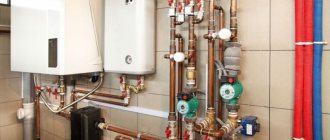
The design of the heating system and the connection diagram of the heating system in combination with a four-way valve look as shown in the image.
Connection diagram for a heating system with a four-way valve Source domotopim.ru
The heating system is made up of the following components:
- 1 – Boiler.
- 2 – Four-way valve.
- 3 – Safety valve.
- 4 – Pressure reducing valve.
- 5 – Filter.
- 6 – Ball valve.
- 7 – Circulation pump.
- 8 – Heating batteries (radiators).
Manufacturers
Four-way valves for heating are produced by companies such as Honeywell, ESBE, VALTEC and others.
Today it is a manufacturer that is included in the list of 100 leading global companies compiled by Fortune magazine.
Honeywell 4 way valve
Four-way valves Honeywell V5442A series are manufactured for systems where the coolant is water or liquids with a glycol percentage of up to 50. They are designed to operate at temperatures from 2 to 110 ° C and at operating pressures up to 6 bar.
Honeywell manufactures valves with connection sizes of 20, 25, 32 mm. Therefore, the Kvs coefficient values range from 4 to 16 m³/h. The series devices operate together with electric drives. For systems with higher power, the flanged series of valves ZR-FA is used.
The Honeywell four-way valve will not cause any difficulties during installation; there are many implementation options.
All its products are economical, reliable and convenient to use in heating, cooling and water supply systems.
ESBE offers a 4-way heating valve with internal thread. The valve body is made of brass. Working pressure 10 atmospheres, temperature 110 degrees (short-term - 130 degrees). The four-way mixing valve is produced in sizes 1/2-2″, with a capacity of 2.5 -40 Kvs.
Valtek offers mixing valves for various purposes, which are designed for durable operation in the engineering system (water heated floor, built-in wall, ceiling heating and cooling, hot water supply). The manufacturer's products can be found anywhere in Russia and the CIS countries.
It cannot be said that a four-way valve for heating will not require financial investment. Installing the device will be expensive, however, on the other hand, the operational efficiency and, as a result, profitability, justifies the monetary costs. There is only the main condition - the presence of a high-quality electrical network, since without it the valve drive will stop working.
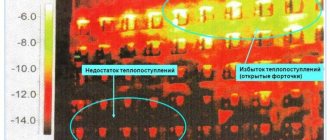
This allows for somewhat automated control, but does not make it possible to constantly maintain a certain temperature at the inlet to the boiler (which is necessary for the safety and durability of the heat generator). Indeed, with large temperature differences, there is a possibility of condensation forming with subsequent corrosion of the heat exchanger, and the intensity of scale formation also increases. If a cast iron heat exchanger is used, cracks may appear in sections of the heat exchanger. In addition, the stress at the connections of boiler parts increases, primarily at the joints and along the welds.
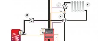
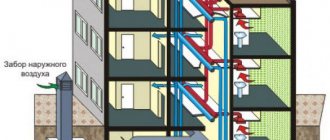
Therefore, for operational safety and durability of the equipment, as well as to achieve the required level of comfort, four-way valves are used to separate the heating and boiler circuits. In Fig. Figure 2 shows a typical diagram using a solid fuel boiler and a hot water storage tank (one outlet from the boiler, after which the coolant is distributed to hot water heating and the heating system). The separation of the boiler circuit and the heating system circuit is carried out using a 4-way valve, which allows for constant circulation in the boiler circuit and, at the same time, in the heating system circuit.
Rice. 2. Installation diagram of a solid fuel boiler to a heating system with forced circulation of coolant and a 4-way valve: 1 - boiler; 2 — automatic boiler control unit; 3 — coolant temperature sensor; 4 - room thermostat; 5 - circulation pump; 6 – heat consumer; 7 - differential valve; 8 - four-way mixing valve; 9 — expansion tank; 10 - hot water boiler; 11 - boiler pump; 12 — shut-off valves; 13 - filter
At the same time, in addition to the extreme positions, in the middle position 50% of the coolant goes into the heating system, mixing with 50% of the coolant returning from the heating system, and the remaining part returns back to the boiler, mixing with the rest of the coolant from the heating system. It is also possible to maintain, in contrast to regulation with 3-way valves, a flow separation constant in other strictly defined proportions. For example, 30% of the coolant is in the boiler circuit, 70% is in the heating system. Or any other ratio (Fig. 3).
Rice. 3. 4-way valve positions
Such constancy of consumption is very important for a solid fuel boiler, since, as we noted above, when using it there are not such wide opportunities to influence the intensity of the combustion process as in gas boilers. The use of an automatic draft regulator allows you to regulate the temperature only at the outlet of the boiler, but not on the return line
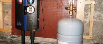
Heating system assembly
The heating system is assembled in the following order:
- A pump is fixed to the return pipe, which is responsible for the circulation rate of the coolant fluid.
- Safety branches are mounted on the inlet and outlet pipes. It is prohibited to install a valve and tap on the latter, due to the high pressure under which they will be exposed.
- A check valve is installed on the water supply pipeline. Its functions will include protecting the system from the negative effects of backpressures and siphon drainages.
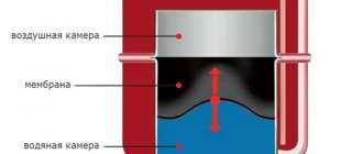
- The expansion tank is located at the highest point of the pipeline. This condition is necessary to reduce the likelihood of circulation problems resulting from water expansion. It can be installed in both horizontal and vertical positions.
- Installation of expansion valve. This is accomplished by installing a thermostatic valve with a double sensor. It is needed to achieve uniform distribution of thermal energy. As already mentioned, when the water temperature rises above 95°C, it transmits a pulse signal to the thermostatic mixer, which opens the cold flow. After the system has cooled down, another signal is given, the valve closes, and the water supply stops.
- The assembly is completed by installing the pressure reducer. It is installed directly next to the inlet pipe of the thermostatic mixer. Designed to reduce the pressure drop when opening the valve and supplying liquid.