Those who want to make a heater with their own hands are not decreasing: the prices for factory-made autonomous heating devices are not encouraging, and their declared characteristics often turn out to be overpriced compared to the real ones. It is useless to make claims: y - the efficiency of heating a room strongly depends on its thermal properties. Cases where compensation for the consequences of an accident that occurred due to the fault of their product are also rare. True, although it is not prohibited by law to make household heaters yourself, trouble caused by a homemade product will be a serious aggravating circumstance for its manufacturer and owner. Therefore, this article further describes how to correctly design and manufacture safe household heaters of several systems, which are not inferior in thermal efficiency to the best industrial designs.
Constructions
Amateur craftsmen build heaters that are often very intricate in design, see photo in Fig. Sometimes they are done carefully. But the vast majority of homemade heating devices described in RuNet have one thing in common: the high degree of danger they create, harmoniously combined with a complete discrepancy between the expected technical characteristics and the actual ones. First of all, this relates to reliability, durability and transportability.
homemade heaters
Make a heater for your home. premises or a camping autonomous one for summer cottages, tourism and fishing, the following systems are possible (from left to right in the figure):
- With direct air heating using natural convection - an electric fireplace.
- With forced blowing of the heater - fan heater.
- With indirect air heating, natural convection or forced air flow - oil or water-air heater.
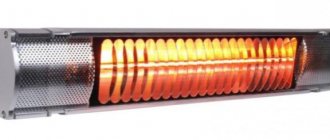
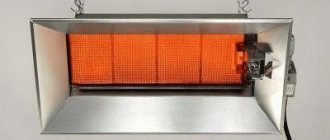
- In the form of a surface emitting thermal (infrared, IR) rays - a thermal panel.
- Fiery autonomous.
The latter differs from a stove, stove or hot water boiler in that most often it does not have a built-in burner/furnace, but uses waste heat from heating and cooking appliances. However, the line here is very blurred: gas heaters with a built-in burner are commercially available and can be made independently. Many of them can be used to cook or reheat food. Here, at the end, a flame heater will also be described, which is not wood-based, not liquid fuel, not gas-based, and certainly not a stove. And the others are considered in descending order of their degree of safety and reliability. Which, nevertheless, with proper execution and in the “worst” samples, fully comply with the requirements for household autonomous heating devices.
Film infrared heater
There are several options for heated floors. One of them is water, the other, no less effective, is infrared. It is easy to assemble using IR film and rod mat. The above-mentioned film has another option for no less useful use - as a coolant for an electric heater.
Film materials that emit infrared waves can be purchased and are commercially available. The choice is great, but manufacturers do not always care about the safety of their products. Pay attention to the composition of the infrared film and refuse to purchase it if you see lead in the instructions. It is extremely dangerous to health!
Important: the “correct” IR film is always accompanied by a quality certificate.
To make an IR heater you will need the following materials and tools:
- 2 sheets of IR film 500 mm by 1250 mm,
- polystyrene (foamed, foil, self-adhesive),
- decorative corner,
- wire with plug (two-core),
- thermostat,
- polymer glue,
- decorative material (ideally natural fabric),
- decorative corners 150 mm by 150 mm.
The process of assembling such a heater will not take much of your time. The main thing is to have all the necessary tools and materials at hand.
- It is necessary to strengthen the thermal insulation on the wall. The thickness of the foamed polystyrene must be at least 5 cm. After removing the protective film, the plate should be pressed against the wall with a self-adhesive layer. In this case, the surface with foil will be directed inside the room.
- You can start the next stage of work only after an hour - let the glue set properly.
- It is necessary to connect the sheets of IR film together in series.
- Apply glue to the back of the film using a spatula or brush.
- Attach the IR film to the polystyrene and leave for 2 hours.
- Attach an electrical cord with a plug and a thermostat to the structure.
- Decorate the heater using a piece of natural fabric and decorative corners.
In the video below, the master shows how he assembled a heater from pieces of IR film.
Thermal panel
This is quite complex and labor-intensive, but the safest and most effective type of household electric heater: a double-sided thermal panel for 400 W in a 12 sq. m room. m in a concrete house heats from +15 to +18 degrees. The required power of the electric fireplace in this case is 1200-1300 W. The cost of making a thermal panel yourself is small. Thermal panels work in the so-called. far (more distant from the red region of the visible spectrum) or long-wave IR, so the heat is soft, not burning. Due to the relatively weak heating of the heat-emitting elements, if they are made correctly (see below), the operational wear of thermal panels is practically absent, and their durability and reliability are limited by unforeseen external influences.
The heat-emitting element (emitter) of a thermal panel consists of a thin flat conductor made of a material with high electrical resistivity, sandwiched between 2 plates - dielectric plates transparent to IR. Thermal panel heaters are made using thin-film technology, and the covers are made from a special plastic composite. Both are unavailable at home, so many hobbyists are trying to make heat emitters based on a carbon coating sandwiched between 2 glasses (item 1 in the figure below); ordinary silicate glass is almost transparent to IR.
This technical solution is a typical surrogate, unreliable and short-lived. The conductive film is obtained either from candle soot or by spreading an epoxy compound filled with ground graphite or electrical carbon onto the glass. The main drawback of both methods is the uneven film thickness. Carbon in the amorphous (coal) or graphitic allotropic modification is a semiconductor with high intrinsic conductivity for this class of substances. The effects characteristic of semiconductors appear in it weakly, almost imperceptibly. But with increasing temperature of the conductive layer, the electrical resistivity of the carbon film does not increase linearly, like that of metals. The consequence is that thin areas heat up more and burn out. The current density in the thicker ones increases, they heat up, they also burn out, and soon the entire film burns out. This is the so-called. avalanche burnout.
In addition, the soot film is very unstable and quickly crumbles on its own. To obtain the required heater power, up to 2 volumes of carbon filler must be added to the epoxy glue. In fact, up to 3 is possible, and if you add 5-10% by volume of a plasticizer - dibutyl phthalate - to the resin before adding the hardener, then up to 5 volumes of filler. But the ready-to-use (not hardened) compound turns out to be thick and viscous, like plasticine or fatty clay, and it is unrealistic to apply it with a thin film - epoxy sticks to everything in the world except paraffin hydrocarbons and fluoroplastic. You can make a spatula out of the latter, but the compound behind it will stretch out in clumps and lumps.
Finally, graphite and coal dust are very harmful to health (have you heard about silicosis in miners?) and extremely dirty substances. It is impossible to remove or wash away their traces; soiled things have to be thrown away, they stain others. Anyone who has ever dealt with graphite lubricant (this is the same finely crushed graphite) - as they say, I will live, I will not forget. That is, homemade emitters for thermal panels need to be made in some other way. Fortunately, calculations show that the “good old”, proven over many decades and inexpensive nichrome wire is suitable for this.
Calculation
Through 3-mm window glass, approx. 8.5 W/sq. dm IR. From the “pie” of the thermal panel emitter, 17 W will go in both directions. Let's set the dimensions of the emitter to 10x7 cm (0.7 sq. dm); such pieces can be cut from culls and cutting waste in almost unlimited quantities. Then one emitter will give us a room of 11.9 W.
Let's take the heater power to be 500 W (see above). Then you will need 500/11.9 = 42.01 or 42 emitters. Structurally, the panel will consist of a matrix of 6x7 emitters with dimensions without frames of 600x490 mm. Let's put it on a frame up to 750x550 mm - ergonomically it works, it's quite compact.
The current consumed from the network is 500 W/220 V = 2.27 A. The electrical resistance of the entire heater is 220 V/2.27 A = 96.97 or 97 Ohms (Ohm’s law). The resistance of one emitter is 97 Ohm/42 = 2.31 Ohm. The resistivity of nichrome is almost exactly 1.0 (Ohm * sq. mm)/m, but what cross-section and length of wire is needed for one emitter? Will the nichrome “snake” (item 2 in the figure) fit between 10x7 cm glass?
Design and drawings of a homemade infrared panel heater
Current density in open, i.e. in contact with air, nichrome electric spirals - 12-18 A/sq. mm. They glow from dark to light red (600-800 degrees Celsius). Let's take 700 degrees at a current density of 16 A/sq. mm. Under the condition of free IR radiation, the temperature of nichrome depends on the current density approximately by the square root. Let's reduce it by half, to 8 A/sq. mm, we get the operating temperature of nichrome at 700/(2^2) = 175 degrees, safe for silicate glass. The temperature of the outer surface of the emitter (without taking into account heat removal due to convection) will not exceed 70 degrees with an outer surface of 20 degrees - it is suitable both for heat transfer by “soft” IR and for safety if you cover the emitting surfaces with a protective mesh (see below).
A rated operating current of 2.27 A will give a nichrome cross section of 2.27/8 = 0.28375 sq. mm. Using the school formula for the area of a circle, we find the diameter of the wire - 0.601 or 0.6 mm. Let us take it with a margin of 0.7 mm, then the heater power will be 460 W, because it depends on its operating current squared. 460 W is enough for heating; 400 W would be enough, and the durability of the device will increase several times.
1 m of nichrome wire with a diameter of 0.7 mm has a resistance of 2.041 Ohms (0.7 squared = 0.49; 1/0.49 = 2.0408...). To obtain a resistance of one emitter of 2.31 Ohms, you will need 2.31/2.041 = 1.132... or 1.13 m of wire. Let's take the width of the nichrome “snake” to be 5 cm (1 cm of margin at the edges). Add 2.5 mm per turn of 1 mm nails (see below), for a total of 5.25 cm per snake branch. The branches will be needed 113 cm/5.25 cm = 21.52..., let's take 21.5 branches. Their total width is 22x0.07 cm (wire diameter) = 1.54 cm. Let's take the length of the snake to be 8 cm (1 cm of margin from the short edges), then the wire laying coefficient is 1.54/8 = 0.1925. In the lousiest Chinese low-power power transformers it is approx. 0.25, i.e. We have plenty of space for the bends and gaps between the branches of the snake. Phew, the fundamental issues have been resolved, we can move on to R&D (experimental design work) and technical design.
OCD
The thermal conductivity and transparency of IR silicate glass vary greatly from brand to brand and from batch to batch. Therefore, first you will need to make 1 (one) emitter, see below, and test it. Depending on their results, you may have to change the diameter of the wire, so do not buy a lot of nichrome at once. In this case, the rated current and power of the heater will change:
- Wire 0.5 mm – 1.6 A, 350 W.
- Wire 0.6 mm - 1.9 A, 420 W.
- Wire 0.7 mm - 2.27 A, 500 W.
- Wire 0.8 mm - 2.4 A, 530 W.
- Wire 0.9 mm - 2.6 A, 570 W.
Note: for those who are literate in electricity, the rated current, as you can see, does not change according to the square of the wire diameter. Why? On the one hand, thin wires have a relatively large radiating surface. On the other hand, with a thick wire, the permissible IR power transmitted by the glass cannot be exceeded.
For testing, the finished sample is installed vertically, supported by something non-flammable and heat-resistant, on a fireproof surface. Then the rated current is supplied to it from an regulated power supply (PS) of 3 A or more or LATP. In the latter case, the sample cannot be left unattended during the entire test! The current is controlled by a digital tester, the probes of which must be tightly compressed with the current-carrying wires using a screw with a nut and washers. If the prototype is powered by LATR, the tester must measure the AC current (limit AC 3A or AC 5A).
First of all, you need to check how the glass behaves. If it overheats and cracks within 20-30 minutes, then the entire batch may be unusable. For example, dust and dirt become embedded in used glass over time. Cutting them is sheer agony and the death of a diamond glass cutter. And such glass cracks at much lower heat than new glass of the same type.
Then, after 1-1.5 hours, the strength of the IR radiation is checked. The temperature of the glass is not an indicator here, because... The main part of the IR is emitted by nichrome. Since you most likely will not have a photometer with an IR filter, you will have to check it with your palms: they are held parallel to the emitting surfaces at a distance of approx. 15 cm from them for at least 3 minutes. Then, for 5-10 minutes, you should feel even, soft warmth. If the IR from the emitter begins to burn the skin immediately, reduce the diameter of the nichrome. If after 15-20 minutes you don’t feel a slight burning sensation (as in the sun in the middle of summer), you need to take thicker nichrome.
How to bend a snake
The design of the emitter of a homemade panel heater is shown in pos. 2 fig. higher; The nichrome snake is shown conditionally. Glass plates cut to size are cleaned of dirt and washed with a brush in water with the addition of any dishwashing detergent, then also washed with a brush under running clean water. “Ears” - contact lamellas measuring 25x50 mm made of copper foil - are glued to one of the covers with epoxy glue or instant cyanoacrylate (superglue). The overlap of the “ear” on the lining is 5 mm; 20 mm sticks out. To prevent the lamella from falling off before the glue has set, place something 3 mm thick (the thickness of the lining glass) under it.
Next you need to form the snake itself from nichrome wire. This is done on a mandrel template, the diagram of which is given in pos. 3, and a detailed drawing is in Fig. Here. The “tails” for annealing the snake (see below) should be given at least 5 cm. The bitten ends of the nails are sanded to roundness on an emery stone, otherwise it will be impossible to remove the finished snake without crushing it.
Drawing of a template for forming a flat nichrome heating element
Nichrome is quite elastic, so the wire wound on the template must be annealed so that the snake holds its shape. This should be done in semi-darkness or low light. The snake is supplied with a voltage of 5-6 V from a power supply of at least 3 A (this is why a fireproof lining is needed on a tree). When the nichrome glows cherry, turn off the current, allow the thread to cool completely, and repeat this procedure 3-4 times.
The next step is to press the snake with your fingers through the plywood strip placed on it and carefully unwind the tails wound on 2 mm nails. Each tail is straightened and shaped: a quarter of a turn remains on a 2-mm nail, and the rest is cut flush with the edge of the template. The remainder of the “tail” of 5 mm is cleaned with a sharp knife.
Now the snake needs to be removed from the mandrel without damaging it, and secured to the substrate, ensuring reliable electrical contact of the leads with the lamellas. Remove with a pair of knives: their blades are slipped from the outside under the bends of the branches on 1-mm nails, carefully pry up and lift the crimped thread of the heater. Then the snake is placed on the substrate and the leads are bent a little, if necessary, so that they lie approx. in the middle of the slats.
Nichrome cannot be soldered with metal solders with inactive flux, and the remaining active flux can corrode the contact over time. Therefore, nichrome is “soldered” to copper, so-called. liquid solder - conductive paste; It is sold in radio stores. A drop of liquid solder is squeezed onto the contact of the stripped nichrome with copper and pressed with a finger through a piece of plastic film so that the paste does not stick out upward from the wire. You can immediately press it down with some flat weight instead of your finger. Remove the weight and film after the paste has hardened, from an hour to a day (the time is indicated on the tube).
The “solder” has frozen – it’s time to assemble the emitter. Along the middle we squeeze a thin, no thicker than 1.5 mm, “sausage” of ordinary construction silicone sealant onto the snake, this will prevent the wire bends from slipping and closing. After this, we squeeze out the same sealant with a thicker roller, 3-4 mm, along the contour of the substrate, retreating from the edge of approx. by 5 mm. We apply a cover glass and very carefully so that it does not slide to the side and pull the snake along with it, press down until it fits tightly, and set the emitter aside to dry.
The drying rate of silicone is 2 mm per day, but after 3-4 days, as it may seem, it is still impossible to take the emitter into work further; you need to let the inner roller that fixes the bends dry. You will need approx. a week. If many emitters are made for a working heater, they can be dried in a stack. The bottom layer is laid out on plastic film, and covered with it on top. Elements following. layers are laid across the underlying ones, etc., separating the layers with film. The stack, for guarantee, takes 2 weeks to dry. After drying, the protruding excess silicone is cut off with a safety razor blade or a sharp mounting knife. Silicone deposits must also be completely removed from the contact lamellas, see below!
Installation
While the emitters are drying, we make 2 identical frames from slats of hard wood (oak, beech, hornbeam) (item 4 in the figure with the diagram of the panel heater). The connections are made by cutting into half the wood and fastened with small self-tapping screws. MFD, plywood and wood materials with synthetic binders (chipboard, OSB) are not suitable, because prolonged heating, even if not strong, is strictly contraindicated for them. If you have the opportunity to cut frame parts from textolite or fiberglass, that’s generally great, but ebonite, bakelite, textolite, carbolite and thermoplastic plastics are not suitable. Before assembly, wooden parts are impregnated twice with a water-polymer emulsion or water-based acrylic varnish diluted in half.
Ready-made emitters are placed in one of the frames (item 5). The overlapping lamellas are electrically connected by drops of liquid solder, as are the jumpers on the sidewalls, forming a series connection of all emitters. It is better to solder the supply wires (from 0.75 sq. mm) with ordinary low-melting solder (for example, POS-61) with inactive flux paste (composition: rosin, ethyl alcohol, lanolin, see on the bottle or tube). Soldering iron - 60-80 W, but you need to solder quickly so that the emitter does not come unglued.
The next step at this stage is to apply a second frame and mark on it where the supply wires are located; grooves will need to be cut for them. After this, we assemble the frame with the emitters using small screws, pos. 6. Take a closer look at the location of the fastening points: they should not fall on live parts, otherwise the fastening heads will be energized! Also, in order to prevent accidental contact with the edges of the lamellas, all ends of the panel are covered with non-flammable plastic with a thickness of 1 mm, for example. PVC filled with chalk from cable channels (ducts for wiring). For the same purpose, and for greater structural strength, silicone sealant is applied to all joints of the glass and frame parts.
The final steps are firstly the installation of legs with a height of 100 mm. A sketch of the wooden leg of a panel heater is given in pos. 7. The second is to apply a protective steel mesh made of thin wire with a mesh size of 3-5 mm to the sidewalls of the panel. Third, the cable entry is designed with a plastic box: it houses contact terminals and a light indicator. Possibly a thyristor voltage regulator and a protective thermal relay. That's it, you can turn it on and warm up.
Thermal painting
If the power of the described thermal panel does not exceed 350 W, a picture heater can be made from it. To do this, foil insulation is applied to the back side, the same one that is used for thermal insulation. Its foil side should be facing the panel, and the porous plastic side should be facing out. The front side of the heater is decorated with a fragment of photo wallpaper on plastic; thin plastic is not such an obstacle for IR. In order for the picture-heater to warm better, you need to hang it on the wall at an angle of approx. 20 degrees.
What about foil?
As you can see, a homemade panel heater is quite labor-intensive. Is it possible to simplify the work by using, say, aluminum foil instead of nichrome? The thickness of the baking sleeve foil is approx. 0.1 mm, seems to be a thin film. No, the point here is not the thickness of the film, but the resistivity of its material. For aluminum it is low, 0.028 (Ohm * sq. mm)/m. Without giving detailed (and very boring) calculations, we will indicate their result: the area of a thermal panel with a power of 500 W on an aluminum film 0.1 mm thick turns out to be almost 4 square meters. m. Still, the film turned out to be a bit thick.
Homemade heat gun
Another option for equipment that you can assemble yourself is an electric heater similar to a heat gun.
To make a home heat gun you will need:
- metal cylindrical container (bucket, cut cylinder),
- heating element - a spiral from an electric stove,
- metal grate,
- fan,
- conductive wires,
- switch.
The heat gun is assembled as follows:
- Using a grinder, the bottom part of the structure of the prepared cylindrical container is cut off. This results in a through workpiece.
- The grid is cut to the diameter of the container. The spiral is fixed on the grid so that the diameter of the installation is smaller than the diameter of the container.
- Horizontal rectangular holes are made on the sides of the container to insert a grid with a fixed spiral. Thus, the spiral is positioned 3 cm from the edge of the container.
- From the spiral, conductive wires are led out of the walls of the container through special insulators. A circuit breaker with additional insulation is fixed on the outside of the container wall.
- A fan is installed on the opposite side of the grille, which is securely fixed to the walls with self-tapping screws. The device is connected to the machine.
- Holes are made along the edges of the body for mounting supports secured with nuts. The finished structure should be as stable as possible.
- Test run of the finished heater. First, the fan turns on, then power is supplied to the coil.
Constructing a home electric heater with your own hands from improvised materials, the cost of which is low, is not particularly difficult, so even a novice master can cope with such a task.
A characteristic feature of modern heaters produced by domestic and foreign industry is their impressive design.
But is it worth spending money on such beauty if you need to heat, for example, a garage in winter or a country house in inclement weather?
In such an unpretentious environment, you can use a homemade device, which, despite all its unpretentiousness, will perfectly cope with the task.
Moreover, making a heater with your own hands due to the simplicity of its design is not at all difficult. Let's get acquainted with some varieties of these devices and find out how and from what you can make a heater with your own hands at home.
heating elements
For heaters: types you will have to buy heating elements: 220 V electrical appliances with open heaters are extremely dangerous. Here, pardon the expression, you need to think first of all about your own skin and property, whether there is a formal ban or not. It’s easier with 12-volt devices: according to statistics, the degree of danger decreases in proportion to the square of the supply voltage ratio.
If you already have an electric fireplace, but it doesn’t heat well, it makes sense to replace a simple air heating element with a smooth surface (pos. 1 in the figure) with a finned one, pos. 2. The nature of convection will then change significantly (see below) and heating will improve when the power of the finned heating element is 80-85% of the smooth one.
Types of heating elements
A cartridge heating element in a stainless steel housing (item 3) can heat both water and oil in a tank made of any structural material. If you buy one, be sure to check that the kit includes gaskets made of oil-heat-gasoline-resistant rubber or silicone.
A copper water heating element for a boiler is equipped with a tube for a temperature sensor and a magnesium protector, pos. 4, which is good. But they can only heat water and only in a stainless steel or enameled tank. The heat capacity of oil is much less than that of water, and the body of a copper heating element in oil will soon burn out. The consequences are severe and fatal. If the tank is made of aluminum or ordinary structural steel, then electrocorrosion due to the presence of a contact potential difference between the metals will very quickly eat away the protector, and then eat through the body of the heating element.
T. called. dry heating elements (item 5), like cartridge ones, are capable of heating both oil and water without additional protective measures. In addition, their heating element can be changed without opening the tank and without draining the liquid from there. There is only one drawback - they are very expensive.
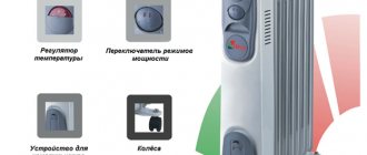
Oil battery
Oil heaters are very popular. Their operating principle is very simple: the oil located inside the pipes is heated by a heating element inserted inside. This device is very easy to manufacture and has good efficiency and safety indicators.
Making your own oil heater is not difficult, you just need to follow the instructions
They do it like this:
- Take a heating element (power - 1 kW) and an electrical cord with a plug for the socket. Some craftsmen install a thermal relay for automatic control. It is also purchased in the store.
- The building is being prepared. An old water heating battery or car radiator will do for this. You can weld the body of the device from pipes yourself if you have welding skills.
- Two holes are made in the housing: at the bottom - for inserting the heating element, at the top - for filling oil and replacing it.
- Insert the heating element into the lower part of the housing and seal the mounting location well.
- Fill in oil at the rate of 85% of the internal volume of the housing.
- They connect control and automation devices and insulate electrical connections well.
After this, the heater is ready for use. It is preliminarily tested in different operating modes.
DIY infrared heater;
Fireplace
Diagram of an electric fireplace with an air heating element and a double convection circuit
You can improve an ordinary electric fireplace, or make your own efficient one based on a purchased heating element, using an additional casing that creates a secondary convection circuit. From a conventional electric fireplace, firstly, the air flows upward in a rather hot but weak stream. It quickly reaches the ceiling and through it warms more of the neighbors' floors, attic or roof than the owner's room. Secondly, the IR coming down from the heating element in the same way warms the neighbors below, the subfloor or basement.
In the design shown in Fig. on the right, downward IR is reflected into the outer casing and heats the air in it. The thrust is further enhanced by the suction of hot air from the inner casing, which is less heated from the outer casing at the narrowing of the latter. As a result, the air from an electric fireplace with a double convection circuit comes out in a wide, moderately heated stream, spreads to the sides without reaching the ceiling, and effectively heats the room.
Heater based on graphite glue and laminate
Graphite glue
Undoubtedly, you cannot ignore the heater for construction, which you need to stock up on two sheets of multilayer plastic with dimensions 1 * 2, epoxy glue, graphite powder, a piece of wire that would have a working plug.
First you need to prepare a dense adhesive solution based on a small amount of epoxy glue with exactly the same amount of graphite.
Then the resulting mass is applied in zigzag strokes to that side of the plastic plate, which is characterized by a rougher surface.
All these strokes become nothing more than graphite conductors, which have high resistance.
Both plastic blanks are glued together, with those sides that have graphite processing, using the same epoxy glue.
Important: To make the structure static, it is placed in a special frame that will hold the sheets together. Terminals made of copper are attached to the graphite conductors-dabs on different sides of the frame.
After the device has completely dried, it can be connected to the standard electrical network. As a result, we should have a very effective, small-sized and inexpensive heater that can easily be mounted on both walls and floors.
The heating temperature will directly affect the ratio of glue and graphite in the adhesive solution, as well as the thickness and total length of the applied strokes. But as practice shows, the average temperature reaches 65 degrees.
Oil and water
The effect described above is also produced by oil and water-air heaters, which is why they are popular. Industrially produced oil heaters are made hermetically sealed with a permanent filling, but it is in no case recommended to repeat them yourself. Without an accurate calculation of the volume of the housing, internal convection in it and the degree of oil filling, a rupture of the housing, an electrical failure, oil spillage and fire are possible. Underfilling is just as dangerous as overfilling: in the latter case, the oil simply tears the housing under pressure when heated, and in the former, it first boils. If you make the housing of a deliberately larger volume, then the heater will heat disproportionately weakly compared to the electricity consumption.
In amateur conditions, it is possible to build an open-type oil or water-air heater with an expansion tank. The diagram of its device is shown in Fig. Once upon a time they made quite a lot of these, for garages. The air from the radiator is slightly heated, the temperature difference between inside and outside is kept minimal, which is why heat loss is reduced. But with the advent of panel heaters, oil-based homemade products are disappearing: thermal panels are better in all respects and are completely safe.
Oil heater device with expansion tank
If you still decide to make your own oil heater, keep in mind that it must be reliably grounded, and you only need to fill it with very expensive transformer oil. Any liquid oil gradually bituminizes. Increasing temperature accelerates this process. Motor oils are designed to allow oil to circulate among moving parts due to vibration. Bituminous particles in it form a suspension that only pollutes the oil, which is why it has to be changed from time to time. In the heater, nothing will prevent them from depositing carbon deposits on the heating element and in the tubes, causing the heating element to overheat. If it bursts, the consequences of oil heater accidents are almost always very serious. Transformer oil is expensive because the bituminous particles in it do not settle into soot. There are few sources of raw materials for mineral transformer oil in the world, and the cost of synthetic oil is high.
Do-it-yourself heater based on the “reflection” principle
Reflective foil screen
One of the simplest devices will be a small sheet of food foil attached to a central heating radiator, which will be directed towards the living space.
Those heat rays that emanate from the radiator are reflected in the surface of the foil onto the heated room, while no heat loss occurs due to unnecessary heating of the walls.
This method is the cheapest, because... costs only for foil and its fastening to the wall.
Heat transfer increases by about 10-20%.
Fiery
Powerful gas heaters for large rooms with catalytic afterburning are expensive, but record-breakingly economical and efficient. It is impossible to reproduce them under amateur conditions: you need a micro-perforated ceramic plate with platinum coating in the pores and a special burner made of parts made with precision precision. At retail, one or the other will cost more than a new heater with a warranty.
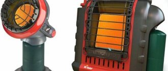
Gas mini camping heaters
Tourists, hunters and fishermen have long come up with low-power afterburner heaters in the form of an attachment to a camp stove. These are also produced on an industrial scale, pos. 1 in Fig. Their efficiency is not so great, but it’s enough to heat the tent until lights out in sleeping bags. The design of the afterburner is quite complex (item 2), which is why factory tent heaters are not cheap. Fans also make a lot of these, from cans or, for example. from automobile oil filters. In this case, the heater can operate both from a gas flame and from a candle, see video:
Video: Portable oil filter heaters
With the advent of heat-resistant and heat-resistant steels in widespread use, lovers of being outdoors are increasingly giving preference to gas camping heaters with afterburning on a grid, pos. 3 and 4 - they are more economical and heat better. And again, amateur creativity combined both options into a combined type mini-heater, pos. 5., capable of working from both a gas burner and a candle.
Drawing of a mini-heater made from scrap materials for a summer residence
A drawing of a homemade mini-heater with afterburning is shown in Fig. on right. If it is used occasionally or temporarily, it can be made entirely from tin cans. For an enlarged version for the garden, cans of tomato paste, etc. will be used. Replacing the perforated mesh cover significantly reduces warm-up time and fuel consumption. A larger and very durable version can be assembled from car wheels, see next. video clip. This is already considered a stove, because... You can cook on it.
Video: heater-stove made from a wheel rim
Heater based on IR port and spiral
This option involves the purchase of an incandescent coil and an infrared port.
The prepared spiral must be placed in a rectangular volumetric block, which must have an electrical connection.
The IR port is connected directly to the finished heater from a block with a spiral.
At this point, the device is basically ready.
The operation of the device is based on the use of the ability of the infrared port to transmit thermal information into space using the infrared range of thermal waves, which form the medium for their propagation.
From a candle
A candle, by the way, is a fairly strong source of heat. For a long time, this property was considered a hindrance: in the old days, at balls, ladies and gentlemen would sweat, makeup would run, and powder would clump together. How they even turned cupids after that, without hot running water and a shower, is difficult for a modern person to understand.
Home mini heater from a candle
The heat from a candle in a cold room is wasted for the same reason that a single-circuit convection heater does not heat well: hot exhaust gases rise up too quickly and cool, producing soot. Meanwhile, making them burn out and give heat is easier than a gas flame, see fig. In this system, a 3-circuit afterburner is assembled from ceramic flower pots; baked clay is a good IR emitter. A candle heater is intended for local heating, say, so as not to tremble while sitting at the computer, but just one candle provides a surprising amount of heat. When using it, you only need to open the window slightly, and when going to bed, be sure to extinguish the candle: it also consumes a lot of oxygen for combustion.
Equipment and accessories
The complete set of fan heaters varies according to the type of installation:
- Floor fan heaters are manufactured static or mobile. The former are equipped with durable legs, the latter – with legs or wheels.
- Wall-mounted units are most often installed in small spaces. They are only stationary and are attached to the wall; they often come with a remote control.
Wall or ceiling heat fans are fixed to the surface of the wall or ceiling using a special bracket or mounting bracket.
Some accessories for heating fans:
- A device for adjusting the fan speed helps to avoid overloads and breakdowns.
- To increase the distance covered by a stream of warm air, a special confuser is sold in stores.
- Controllers, on which commands are set and functions are switched, are built into the device during assembly or sold separately.
- For large models, special trolleys are sold, which makes the stationary floor heater mobile.
- Thermostats and controllers are sold separately.
- The mounting console rotates the device body in any direction.
Typically, heating equipment is powered electrically. However, water-powered air ventilation devices are produced. Hot water gives off heat to the heating apparatus, and due to this it works.