Heating schemes
I'll start with a small lyrical digression.
Heating systems with water as a coolant are divided into:
- Open and closed;
- With forced circulation and gravity.
What does this division mean?
Open and closed
An open expansion tank is installed at the top point of the open circuit.
Open expansion tank.
It combines three functions:
- Allows you to add water, compensating for its leakage and evaporation;
- Accommodates excess water during its expansion accompanying heating;
- Serves to remove air pockets.
For the air vent to work through an open tank, the bottling must be laid with a constant slope from the tank to the boiler heat exchanger.
A closed system does not communicate with the atmosphere and operates with excess pressure. Its main problem is that when heated, the coolant increases in volume and may well rupture pipes and heating devices.
Rupture of a polypropylene heating pipe.
Gravitational and forced
The operation of a heating system with forced circulation is ensured by a circulation pump - a low-power device with a screw or centrifugal impeller mounted on the shaft of an electric motor. It provides a sufficiently high flow rate in the pipes and, accordingly, fast and uniform heating of heating devices.
Circulation pump.
The Achilles heel of forced circulation is the energy dependence of the pump. In conditions of short-term outages, the situation can be saved by an uninterruptible power supply, but in the event of a prolonged absence of electricity, the heating will cease to perform its functions.
A system with natural circulation, which is ensured by the difference in the density of cold and hot water, does not have this drawback.
The principle of its operation is extremely simple:
- Water heated in the heat exchanger of a heating boiler (usually solid fuel) is displaced through the accelerating manifold into the upper part of the circuit by colder coolant masses;
- From there it moves by gravity along the circuit, gradually releasing heat through the radiators;
- The cooled water is returned to the heat exchanger, and after it is heated, the cycle repeats.
The principle of operation of the gravitational system.
Introduction to the theory is completed. Let's move on to practice.
Gravity open system
Open gravity heating system.
Elements
In a gravity open system, the piping of a pellet heating boiler or other solid fuel heat source includes:
- Acceleration manifold. In essence, it is just a short vertical bottling section immediately after the kettle;
- Open expansion tank. As a rule, its volume is taken approximately equal to 10% of the coolant volume in the circuit.
The easiest way to find out the capacity of the circuit is by filling the heating system with water and draining it into a bucket of known volume or any other measuring container.
In addition, shut-off valves are installed at the inlet and outlet of the boiler. They allow you to turn off the heat exchanger for repairs or maintenance without dumping the entire volume of coolant.
Such taps are installed in any system, regardless of its type and heat source.
Shut-off valves at the inlet and outlet of the electric boiler.
Scheme
It is extremely simple: the expansion tank is mounted at the top filling point after the accelerating manifold. Optionally, it is equipped with a tap for filling the circuit with water. A tap is installed at the lowest point of the system to completely drain the coolant: it will be useful if the house is left without heating in cold weather.
The boiler is installed at the lowest point of the circuit (usually in a basement or pit). The height difference between its heat exchanger and the radiators, in fact, ensures stable circulation: thanks to this difference, the cooled water continues to move by gravity.
The hydraulic pressure in the system is equal to the height H.
Nuances and piping options for different types of boilers
General recommendations from experienced professionals:
The installation scheme is selected individually. The boiler is installed in accordance with SNIiP rules below the level of heating devices. Before lining with polypropylene, the floor-standing boiler is installed on a metal or concrete base. Forced ventilation and emergency lighting systems are recommended for all unit options. A coaxial chimney is included in the piping of a device operating on gas fuel, which is sealed at all joints during installation. After completing the piping of the boiler unit and chimney, proceed to installing a safety system in the following order: medium pressure devices (pressure gauges), protective devices and then an automatic air vent. The manifold circuit is made of a 1.25-inch PPR pipeline; protective devices, a circulation pump, a hydraulic arrow and an air vent are installed according to the movement of the medium. To supply the heating coolant to the heating devices, 3 branches of a 1.0-inch PPR pipe are removed from the comb, and the rest are closed with plugs. Connect heating and return devices. In a combined heating system, the underfloor heating circuit is equipped with an independent pump, while the expansion tank is installed between the hydraulic valve and the boiler unit. The piping of the boiler unit is completed by installing a drain valve; it is also used to fill the circuit, but it is better if these are two independent valves
The installation point depends on the chosen system, but there are general conditions - the drain valve is installed at the lowest point, which is especially important if you plan to mothball the system in winter so that there is no water left in it.
Gas equipment
The piping of such equipment with polypropylene pipes is carried out with an independent circuit and a circuit pump that creates operating pressure in a small section of the network from the source to the distributor.
It is allowed to tie a gas unit with such pipes without steel pipes, since the heating temperature at the supply does not exceed 80 C.
In a gas-powered unit with a cast-iron boiler, a heat accumulator is installed, which helps balance the hydraulic regime and prevents sudden temperature changes that affect fragile cast-iron heating surfaces. When piping 2-circuit boilers, it is additionally necessary to place fine and coarse water filters.
Electric heater
Tying an electric boiler with polypropylene is quite acceptable. The boiler has the highest rating for a protective system that prevents the water in the unit from boiling, with subsequent formation of steam and pipe rupture. The heating process stops when the power supply to the electric heating elements is turned off.
In addition, the system has built-in hydraulic accumulators and devices for relieving excess pressure of the environment, which can form during a sudden power outage and stopping the pump for pumping hot water to heating devices and water collection points.
Solid fuel boiler piping
Solid fuel models
This is the most problematic unit for piping plastic pipes. For it, the installation of a protective meter pipe at the inlet/outlet of the medium is mandatory in order to protect them from overheating. For systems with pump circulation, an additional backup power supply device will be required to continue cooling the boiler in the event of an emergency shutdown of the main source of electricity. In addition, a small gravity circuit is made with a small number of connected batteries to cool the boiler heating surfaces until all the fuel burns out.
According to the requirements of fire safety rules, the solid fuel boiler is covered with a protective casing, which significantly reduces heat loss from the walls of the combustion chamber to the boiler room and, consequently, the negative impact on PPR pipes
A small reminder for the installation of plastic pipes - the quality will be determined not only by the installation work, but also by the selected range of pipes. You should purchase all main and auxiliary boiler room equipment only certified from reputable suppliers. Polymer pipes do not require insulation work or painting, scale and corrosion do not form on them, and they are characterized by high noise insulation. The cost of the material is lower, and the pipes are lighter than those made of metal, so installation can be done by yourself.
Open system with forced circulation
Open system with pump.
Elements
For obvious reasons, an accelerating collector is not needed in this case. Its functions are performed by a circulation pump.
When choosing a pump, you should pay attention to its performance. It is selected depending on the thermal load on the circuit (read: boiler power) according to the following table:
| Thermal load, kW | Productivity, m3/hour at flow rate 0.6 m/s |
| 6 | 0,25 |
| 8 | 0,35 |
| 16 | 0,7 |
| 24 | 1 |
| 40 | 1,6 |
Parameters of some circulation pumps.
You can ignore the pressure created by the pump when choosing it; its minimum values are quite sufficient for a private house of any reasonable size. For reference: the heating system of an apartment building forces a pressure of only 2 meters to circulate (which corresponds to an excess pressure of 0.2 kgf/cm2).
Scheme
The circulation pump is installed, as a rule, in front of the boiler in the direction of the coolant flow: in this section of the circuit the coolant temperature is minimal.
A slight change in the configuration of the circuit will allow it to work with both forced and natural circulation:
- The pump does not cut into the filling gap, but parallel to its section;
- A ball valve or check valve with minimal hydraulic resistance (usually a ball valve) is installed between the taps.
Pump insertion into the gravity filling system.
When the pump is running, the bypass between the taps is closed. When the power supply is interrupted, the tap or check valve opens and the heating system continues to operate as a gravity system.
Rules for piping a gas unit
An owner planning to use heating with blue fuel needs to understand the rules for arranging equipment. Before piping a floor-standing gas boiler with your own hands, follow the rules:
- Regulatory documents provide for the installation of the unit only if the design has been properly completed.
- The technical conditions for drawing up the document are provided by the fuel supplier. This organization also participates in the coordination of papers.
- The placement of the generator and its wiring can be done independently, but in strict accordance with the adopted project.
- The circuit cannot be connected to the main gas pipe, because This is done by specialized companies with issued permission. Most often they are fuel suppliers.
Accommodation requirements
You cannot place a gas generator in any room; there are restrictions for this. The installation of an exhaust hood and the organization of fresh air supply are mandatory. The objectives of the scheme include replacing the volume of atmosphere in the boiler room three times per hour. To find out the indicator, multiply the width, length and height of the room to calculate the volume. The resulting value is multiplied by three.
In a similar way, the exchange of atmosphere in a room is determined for a system with a closed combustion chamber. For units installed in an open circuit and consuming ambient air, the atmospheric flow rate is added to three times the volume. The value is taken from the technical maintenance documentation for the boiler.
According to building regulations, installation of a gas generator is permitted in certain areas of the house:
- with a power of no more than 60 kW, it is placed in the kitchen;
- in a room where one wall is external;
- in independent verandas to the house;
- in a separate heating block building.
The unit cannot be installed in living rooms or bathrooms. When installed in a kitchen, the ceiling is made from the floor at a height of 2.5 m or more. In this case, to calculate the volume of the room, it is taken into account that the initial figure is 15 m³, and for each kilowatt of unit power, 0.2 m is added. For example, for a 15 kW boiler, a kitchen volume of 18 m³ (15 + 15 × 0.2) is required.
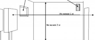
Be sure to make a window in the wall or frame (large window sashes do not count). Air passage is ensured with a minimum vent area of at least 0.25 m³. When placing gas equipment in other areas of the house, the requirements remain the same. When placing the unit, the following rules regarding distances must be followed:
- from the front side (each protruding element) to the wall fence - 1 m;
- for repairs, passages of 0.6 m or more are left on the sides;
- at the back for connecting the smoke duct and maintenance - 0.6 m.
When choosing a wall-mounted device or when placing it in a cabinet, similar intervals are followed. The boiler room must have natural light. The opening area is equal to the volume of the room multiplied by 0.03 m². For partitions, fireproof material is used that can withstand fire for 45 minutes.
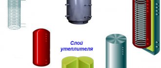
Closed system
Elements
Piping a boiler room in a private house with a closed heating system includes:
- Diaphragm expansion tank. It is a container divided by a rubber membrane into compartments for air and coolant. Unlike liquids, air compresses perfectly and compensates for the increase in volume of water or antifreeze;
The device of the membrane tank.
The volume of the tank in this case is taken equal to approximately 10% of the volume of the coolant. That, in turn, in a balanced system is approximately equal to 15 liters per kilowatt of boiler power.
- Safety valve. The valve releases the coolant when the upper limit of the permissible pressure is reached;
Safety valve with drain tube.
Constant activation of the safety valve indicates insufficient volume of the expansion tank.
- Automatic air vent. It helps get rid of air pockets that impede circulation;
Automatic air vent device.
- Pressure gauge for visual pressure monitoring.
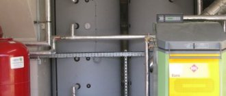
Three in one: boiler safety group.
In the case of a forced circulation circuit, the boiler piping circuit predictably includes a circulation pump.
Scheme
Both the safety group (air vent, pressure gauge and valve) and the expansion tank, in theory, can be mounted at any point in a closed circuit. In practice, when installing a heating system with your own hands, the tank is usually placed in front of the boiler , at a distance of at least 8 filling diameters after the pump or at least two filling diameters in front of the pump.
Why is this so?
- The minimum coolant temperature increases the service life of the tank membrane;
- The absence of turbulence from the pump impeller also has a beneficial effect on the service life of the membrane.
The safety group is most often installed at the boiler outlet.
Arrangement of strapping elements.
Optional elements
What other elements can be included in the piping of a floor-standing or wall-mounted boiler?
Thermal accumulator
This is the name of a metal or polymer tank with thermally insulated walls. As the name suggests, it serves to store thermal energy.
This is useful in two cases:
- When using a solid fuel boiler. Heat accumulation allows you to increase the period of time between lighting and operate the boiler at rated power (and, accordingly, with maximum efficiency);
- When heating the house with an electric boiler and having a two-tariff meter. At night, when the price of a kilowatt-hour of electricity is minimal, the boiler heats water in the heat storage tank, and during the day the accumulated heat is used to heat the home.
Heat accumulator in a home boiler room.
The use of a heat accumulator implies the presence of two circuits, at least one of which operates with forced circulation. The first ring connects the boiler heat exchanger and the tank, the second - the heat accumulator and heating devices.
Connection diagram of the heat accumulator to the boiler and heating circuit with recirculation.
Hydroarrow
Hydraulic arrow with pipes for connecting several circuits.
In essence, it is just a thick pipe with several inlets and outlets. The function of the hydraulic arrow is to synchronize the operation of several circuits with different coolant temperatures (for example, radiators and heated floors).
The water temperature in the heated floor pipes is no more than 40 degrees.
Each circuit is equipped with its own pump and (in the case of a low-temperature circuit) a three-way valve that recirculates the coolant.
In some cases, the function of a hydraulic arrow is performed by a heat accumulator.
How is this possible?
Inside the tank, slowly circulating water is divided by temperature: the hottest (and least dense) coolant collects in the upper part of the tank, the coldest in the lower part.
By drawing water from pipes located at different heights, you can obtain any temperature in the range from boiler supply temperature to room temperature.
The photo shows the connection of the heat accumulator to multi-temperature hot water systems and heated floors.
Collector
Heating manifold.
One of the problems with connecting heating devices in series is the temperature variation between them. The supply radiators are always hotter than the return radiators, which leads to uneven heating of the rooms in the house.
The manifold allows you to connect several convectors, radiators or underfloor heating circuits in parallel. Each collector outlet is equipped with its own tap or throttle, allowing independent shutdown and adjustment of devices.
Manifold heating distribution.
Indirect heating boiler
Typically, to heat hot water, it is practiced to use a double-circuit boiler with a flow-through heat exchanger.
However, this solution has a couple of unpleasant drawbacks:
- Simultaneous operation of heating and instantaneous water heater requires a large power reserve. If you have an electric boiler and a power of 10 kW is allocated to your house, you will have to choose between warm rooms and a hot shower;
- Most instantaneous heaters do not allow precise control of the outlet water temperature. Trying to take a shower or wash the dishes becomes a constant battle with the taps.
An indirect heating boiler is a typical storage water heater without both problems. It connects to the heating circuit and takes some of the heat from the coolant.
Indirect heating boiler.
In summer, circulation occurs in a small circle - between the boiler and the boiler.
Connecting the boiler to the boiler.
Piping of a mounted high-power condensing boiler
Conventionally, the installation diagram (we are considering the Victrix 50 boiler as an example) can be divided into several connection stages: ❏ safety kit; ❏ storage boiler; ❏ solar collector; ❏ hydraulic separator. Let's look at each stage in detail. Safety kit
When connecting a boiler with a power of more than 35 kW, European legislation requires paying closer attention to safety issues.
Therefore, a special safety kit is provided, which includes a safety thermostat, a maximum water pressure switch (4 bar), a pressure gauge and a system filling valve (sleeve for connecting the thermal cylinder of the gas shut-off valve). There are also fittings for connecting an expansion tank and a sleeve for an immersion alcohol thermometer. The pressure switch and overheating thermostat have manual unlocking and are connected in series to the boiler power circuit (Fig. 2). The response limit of safety devices is adjustable and is 3 bar and 105 °C, respectively. This kit allows for compact, quick and reliable installation of safety devices, and also guarantees reliable protection against emergency situations under any circumstances. Storage boiler
Since the boilers are single-circuit, it is proposed to use a storage boiler to meet the needs for hot water.
Several standard sizes of boilers are offered, with a capacity from 80 to 200 liters. The boilers have a rectangular white body. The material used to make the boiler body and coil is high quality food grade stainless steel. To reduce heat loss, the boiler is enclosed in highly efficient polyurethane foam insulation. The boilers are equipped with spiral heat exchangers with a large heat exchange surface, which are connected in a counterflow circuit (Fig. 3). This allows you to quickly heat the accumulated water supply. To ensure the preparation of a large volume of hot water, you can use two 200 liter boilers, in which the coolant and sanitary water circuits are connected in parallel. To connect the boiler to the boiler, you must use a special kit, which consists of adapters and a three-way valve. As with all other mounted boilers, operation in hot water supply mode is based on the principle of strict DHW priority. Connecting solar collectors
A special feature of 200-liter boilers is the ability to work with solar collectors.
In Fig. Figure 4 shows an example of connecting solar collectors to a heat supply system based on a condensing boiler. High-quality solar collectors and a home heating system coordinated with them make it possible to consider the economic use of solar energy as a necessary condition for building an effective system. In our latitudes, the total radiation (reflected and direct) under optimal conditions (cloudless clear sky, middle of the day) is a maximum of 1000 W/m2. Solar collectors, depending on their type, allow the use of up to 75% of the total radiation. It only remains to note that, from our point of view, the combination of a condensing boiler + solar collector (heat pump) is the most promising direction for the further development of autonomous heat supply systems. Hydraulic separator
Since the boiler is designed to carry a significant heat load, this requires the presence of separate heating system circuits with zone control. Therefore, the issue of independent control of circuits becomes relevant. There is a possibility of a change in the amount of coolant circulating through the boiler, which adversely affects its hydraulic mode. A natural solution in this situation is the use of a hydraulic separator (hydraulic arrow). At the same time, a transition is made to pipes of larger diameter, which makes it possible to connect the “hydraulic arrow” directly to the supply and return distribution manifolds. For one boiler, a compact solution for this unit is proposed, in the form of a rectangular pipe (Fig. 5). This unit is located directly under the boiler, which makes it possible to significantly reduce the dimensions of the installation. Since the collector is installed horizontally, to remove sludge from the heating system, it is necessary to install a sediment filter on the return line, in front of the collector.