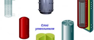
The wiring diagram for boiler rooms for a private house with a heat accumulator and a standard solid fuel boiler is one of the most reliable and popular combinations. The construction of the diagram begins with the arrangement of the piping of the solid fuel boiler, as well as the placement of the buffer tank. This element is installed in order to obtain an additional natural circulation circuit. This creates an alternate path along which water will be directed in the event of an unplanned short-term power outage and a sudden stop of the pump.
Gravity circuit
Let's consider a circuit with natural circulation - gravitational. When drawing up a plan, we avoid bends and try to minimize the number of bends so as not to create unnecessary resistance. Based on the size of the pipes of the boiler used, we select the diameter of the pipes for the circuit. The standard option is no more than 1.5 inches.
The coolant circulates within the gravity circuit without the help of a pump due to the temperature difference created. If the circulation of hot water stops due to a power outage or for another reason, the solid fuel boiler will boil. To avoid this dangerous situation, an additional gravity circuit is used to prevent an accident if the pump stops.
Sometimes the temperature of a solid fuel boiler increases and can exceed the limit of 100 degrees. For this reason, we tie the circuit with metal pipes. We add a pump to the intended circuit. To do this, we are planning a workaround, where we install a safety leaf check valve on a dedicated section of the gravity circuit. We select a valve with minimal resistance. An adapter with standard resistance may interfere with coolant circulation.
In normal mode, the circulation pump creates pressure on the valve, keeping it closed. In this case, water circulates freely along the usual path. When the pump stops, the boiler continues to heat the water, but the built-in valve will work and will not allow water to flow through the main circle.
Adding hot water and adding valves
In order for the system to work, it is necessary to ensure automatic addition of hot water to the return line. This way we increase the temperature of the water entering the boiler. If too cold coolant gets into it, the boiler can quickly fail. There are several common piping schemes with the addition of a return line. We use a three-way thermostatic mixing valve. Installing this valve allows you to create a small circle of circulation of the coolant, as a result of which the heating of the boiler will accelerate. This approach prevents the formation of condensation, thereby protecting the heat exchanger from breakdowns due to significant temperature differences.
Let's imagine a simulated situation. We will set the built-in petal valve to activate when the temperature reaches 55 degrees. When the boiler starts, the water in the system is not heated and while it is cold, the valve closes and lets the medium flow in a small circle. After the supply water warmed up to a threshold value of 55 degrees, the valve opened slightly and began to mix in cooled water from the return. At the next stage, the entire barrel is heated, and the return temperature will also rise above 55 degrees. At this point, the valve will switch completely and release water through the large ring.
After connecting the return line to the solid fuel boiler, we add a pressure relief valve. It is necessary in case of exceeding performance indicators. The solid fuel boiler has a special hole for mounting the valve. In other models, the valve can be installed through a tee. We include an expansion tank in the system. After this, to complete the piping on the heat generator side, it is necessary to connect the electric boiler. It is included in the circuit in parallel with an already installed solid fuel boiler.
We have two feeds, and check valves need to be installed on each of them. This is done so that the pump of one of the boilers does not pump water along the working circuit in the opposite direction to the other. Let us remind you that on a solid fuel boiler we use not a regular valve, but a reed valve.
How to choose the right boiler connection diagram?
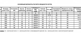
In order to keep the house warm, it is not enough to know what heating schemes are available with a solid fuel boiler. Craftsmen who have been creating heating systems for many years give the following recommendations:
- When creating a drawing of a heating circuit for a solid fuel boiler, you should first familiarize yourself with the types and operating principles of such heat generators. This can be a constant or long-burning heater, a pyrolysis or pellet unit, or a buffer. Each of these devices has its own operating criteria, which may be disadvantages for some, and advantages for others.
- To get an ideal heat supply scheme, you need to be able to combine the functioning of the boiler with the tank, since this element accumulates thermal energy. This is justified by the fact that the element heating the water can change its temperature in the range from 60 to 90 degrees. There is no constant indicator. Since solid fuel boilers are inert devices, this distinguishes them favorably from gas, diesel and electric analogues.
- When choosing a heating scheme, you need to objectively assess the risk of power outages. If there are frequent power outages in the area, then a system with a water pump will not only not pay for itself, but may quickly fail. Therefore, it is better to choose a type of heating with natural circulation.
- When choosing a piping, it is worth considering in advance the safety lines between the boiler and the tank. They are located at the points of the inlet and outlet pipes so that they are as close as possible to the water heater. Also, to achieve maximum effect, you need to try to keep the distance between the boiler and expansion tank to a minimum. But it is no longer possible to install safety valves or taps here.
- If a scheme with a pump was chosen, then it is installed on the return pipe, as close as possible to the heat generator. Thus, even if the lights are turned off and the pump stops working, the water will continue to move along the circuit, that is, minimal heat will be retained. The device must be installed along a bypass route. Only then will it be possible to disconnect it from the network (if necessary), and shut off the circuit itself using taps.
- There is such a thing as bypass. These are jumpers with taps that are placed between the supply line and the return pipe. This arrangement facilitates the return of “extra” hot water when the volume changes through the thermostat.
- A stainless steel valve must be installed in the chimney pipe. Since there is moisture in the smoke, albeit in small quantities, it is this that can provoke the destruction of the internal part.
Tying is a process that deserves special attention. Therefore, they design and install it only if they have complete confidence in their abilities.
Connecting a solid fuel boiler and buffer tank
The simplest would be a piping scheme containing a buffer tank with a pre-installed DHW coil. The advantage of this option will be significant space saving in the boiler room due to the absence of a separate boiler. Another additional benefit is the modest savings on investment due to the absence of the need to purchase and install another unit. This option simplifies the system maintenance process, since there will be no problems fighting bacteria.
In summer, a heat accumulator with a DHW coil becomes a full-fledged indirect heating boiler. The pump is connected to the circuit with a standard inch pipe; a ¾ or inch pipe is well suited for an electric boiler. If you plan to install a buffer tank with a volume of at least 1000 liters, then it is more economical and expedient to raise the return from the electric boiler a little and connect the main circuit not from below, but above, to the middle terminals of the heat accumulator. With this scheme, the boiler will not constantly heat the entire volume, which will reduce its depreciation rate. This parameter depends on the terms of reference.
If you need to connect not a solid fuel boiler, but a gas boiler, then the same circuit diagram is used as for an electric one. It should be noted that in the scheme we are considering, a standard electric boiler already contains everything necessary:
- pump;
- pressure meter;
- safety valve.
If you choose a model that does not have these parts, the boiler will have to be tied accordingly.
How to connect a solid fuel boiler
The canonical connection diagram for a solid fuel boiler contains two main elements that allow it to function reliably in the heating system of a private home. This is a safety group and a mixing unit based on a three-way valve with a thermal head and a temperature sensor, shown in the figure:
The always open output of the mixing valve (the left pipe in the diagram) must be directed to the pump and heat generator, otherwise there will be no circulation in the small boiler circuit
Note. The expansion tank is not shown here - it must be connected to the return line of the heating system in front of the pump (in the direction of water flow).
The presented diagram shows how to connect the unit correctly and is used with any solid fuel boilers, including pellet ones. You can find various general heating schemes - with a heat accumulator, an indirect heating boiler or a hydraulic arrow, in which this unit is not shown, but it must be there. The method of protecting against moisture loss in the firebox is discussed in detail in the video:
The task of the safety group, installed directly at the outlet of the supply pipe of a solid fuel boiler, is to automatically relieve pressure in the network when it rises above a set value (usually 3 Bar). This is done by a safety valve, and in addition to it, the element is equipped with an automatic air vent and a pressure gauge. The first releases the air appearing in the coolant, the second serves to control the pressure.
Attention! The installation of any shut-off valves is not allowed on the section of the pipeline between the safety group and the boiler. If you installed a ball valve to cut off and repair group parts, remove the handle from the stem.
How the scheme works
The mixing unit, which protects the heat generator from condensation and temperature changes, operates according to the following algorithm, starting from kindling:
- The firewood is just starting to burn, the pump is on, the valve on the side of the heating system is closed. The coolant circulates in a small circle through the bypass.
- When the temperature in the return pipeline rises to 50-55 °C, where the attached remote-type sensor is located, the thermal head, at its command, begins to press the three-way valve stem.
- The valve slowly opens and cold water gradually enters the boiler, mixing with hot water from the bypass.
- As all the radiators warm up, the overall temperature increases and then the valve closes the bypass completely, passing all the coolant through the heat exchanger of the unit.
An important nuance. Paired with a 3-way valve, a special head with a sensor and capillary is installed, designed to regulate the water temperature in a certain range (for example, 40...70 or 50...80 degrees). A regular radiator thermal head will not work.
This piping scheme is the simplest and most reliable; you can easily install it yourself and thus ensure the safe operation of the solid fuel boiler. There are a couple of recommendations regarding this, especially when piping a wood-burning heater in a private house with polypropylene or other polymer pipes:
- Make the section of the pipe from the boiler to the safety group from metal, and then lay plastic.
- Thick-walled polypropylene conducts heat poorly, which is why the surface-mounted sensor will openly lie, and the three-way valve will lag. For correct operation of the unit, the area between the pump and the heat generator, where the copper flask is located, must also be metal.
Connecting with copper pipes will not protect polypropylene from destruction in the event of overheating of the TT boiler.
But it will allow the temperature sensor and safety valve on the safety group to work correctly. Another point is the installation location of the circulation pump. It is best for him to stand where he is shown in the diagram - on the return line in front of the wood-burning boiler. In general, you can install the pump on the supply side, but remember what was said above: in an emergency, steam may appear in the supply pipe.
The pump is unable to pump gases, so when the chamber is filled with steam, the impeller will stop and the coolant circulation will stop. This will speed up a possible explosion of the boiler, because it will not be cooled by water flowing from the return.
Way to reduce the cost of strapping
The condensate protection circuit can be reduced in cost by installing a three-way mixing valve of a simplified design that does not require connecting an overhead temperature sensor and thermal head. It already has a thermostatic element installed, set to a fixed mixture temperature of 55 or 60 °C, as shown in the figure:
Special 3-way valve for solid fuel heating units HERZ-Teplomix
Note. Similar valves, which maintain a fixed temperature of mixed water at the outlet and are intended for installation in the primary circuit of a solid fuel boiler, are produced by many well-known brands - Herz Armaturen, Danfoss, Regulus and others.
Installing such an element definitely allows you to save on piping the TT boiler. But in this case, the possibility of changing the temperature of the coolant using a thermal head is lost, and its deviation at the output can reach 1-2 °C. In most cases, these shortcomings are insignificant.
Connection to the heating system
We connect the prepared circuit directly to the heating system. From a safety point of view, it must be remembered that a solid fuel boiler can produce an excessively high temperature at certain moments. The storage barrel can contain water at a temperature of 90-100 degrees. This is too much for standard home heating radiators. You can get seriously burned if accidentally touched. For this reason, it is necessary to add another mixing valve to the circuit. He will mix cooled water into the circuit.
If the house has heated floors, it is possible to connect them to the radiator circuit for return flow. Another pump will need to be installed. The connection will go to the mixing unit. Due to the high temperature, water is not drawn directly from the heated heat exchanger, but through a safety mixing valve. This part is installed so that when working with the system and checking it, you do not get scalded by hot steam.
At the next stage, we connect the coolant recirculation line in the system through a special pump. We arrange check valves in the circuit in accordance with the diagram. With this complete set of functional elements, let's move on to the fittings.
Another filter needs to be installed in front of the boilers. Then we install additional automatic air vents at the highest points of the system. Next, we ensure that the system is drained and filled. To do this, we arrange the ball valves so that in the future we can carry out technical inspection and repair of equipment without draining the coolant from the circuit. Cranes are needed for:
- expansion tank;
- boilers;
- pump
In cases where boilers do not have standard thermometers, they are installed additionally. You will also need two control thermometers located on the buffer tank. They will make it easier to monitor the operation of the system and set it up.
Connection requirements
It was already mentioned above that before installing a heating system, you must first study the necessary requirements and standards. The functionality of the entire system depends on this.
Heating efficiency is directly related to whether the system is connected to a water circuit or not. When buying a solid fuel boiler, you need to carefully read the operating instructions. Such documents not only explain the technical characteristics of the device, but also indicate in detail how the unit should operate. For example, the minimum outlet temperature should be 55 degrees, while the inlet temperature should be 45 degrees. Otherwise, condensation will form. It is for such purposes that you need to create the correct diagram for connecting the boiler to the system.
There are a number of other features you need to know:
- When choosing a place to install the device, it is important to remember that it is an ideal horizontal hard surface. In this case, it must have a strictly vertical position. Therefore, experts recommend first making a cement screed in the boiler room, the thickness of which should be at least 5 cm. They also install a backfill of the same thickness. It is important to say here that to install the expansion tank you need to choose the highest point, for which the attic is usually chosen.
- The heating system must have a chimney, which is equipped with a valve. This part is selected from stainless steel. A collection tank is installed at the bottom of the chimney in which all condensate will accumulate. Since smoke with various kinds of impurities will have to pass through such a pipe, over time a coating will begin to form on the inner surface. Accordingly, it is necessary to create conditions so that the chimney can be put in order, for which windows are installed along the entire length. It is important that they are easily accessible.
- If the soot removal pipe has to pass through low-heated rooms in the house, then such areas must be insulated. This will not only help avoid the formation of additional condensation, but will also significantly extend the service life of the material itself.
- When creating a heating circuit, it is necessary to install a safety valve. This is justified by the fact that solid fuel boilers must work only with a water circuit where there is a pressure of 2 kg/cm3, and the temperature should not exceed 90 degrees. Therefore, the valve will become a fuse in case of any failure.
In fact, all technological nuances are always indicated in the instructions for the unit. Accordingly, before choosing a boiler piping scheme, you need to carefully study the documentation.
Insulation of fittings
Let's consider the issue of the need to insulate the fittings. Long pipe lengths, many fittings and high operating temperatures in the system lead to heat loss. At finished facilities, heating equipment that is not properly insulated overheats the surrounding space. In the room where the boiler and heat accumulator are installed, the temperature can reach plus 27 degrees in severe frost. Fuel is wasted and system efficiency decreases. After insulating the pipes, it is possible to gain a few degrees and reduce fuel consumption.
When insulating the fittings, you must remember that when working from the side of the boilers, the pipes become very hot, since they can transport water hotter than 100 degrees. Polyethylene foam insulation is not suitable in this case. It can only be installed in another part of the circuit on the side of the radiators of the heating system. In a boiler room, it is better to put rubber insulation that is more resistant to heat on hot pipes. It is also worth additionally insulating fittings and other fittings.
For safety reasons, it is not recommended to insulate pumps. This equipment is limited to exceed ambient temperature limits. If you insulate the pumps from the boiler side, you can insulate them too much, and this is unacceptable.
Connection diagram with boiler
Let's consider another wiring diagram for a solid fuel boiler, in which in addition to the heat accumulator there is a boiler. We will not redo the boiler part, we will leave it unchanged. Similar to the previous diagram, we will connect the entire heating system. Only the indirect heating boiler added to the planned circuit will be new. Inside the model we have chosen there is a coil through which the heated coolant passes. Thanks to this, the water is heated directly and pumped using a special pump. Based on the experience of previously used circuits, I recommend using the terminals connected to the boiler away from those connected to the boiler itself and heating radiators.
Another expansion tank must be installed at the outlet of prepared hot water from the boiler. After this, we install a petal safety valve at the entrance to the cold water system. According to this scheme, it is permissible to supply hot water directly to the bathrooms without additional inserts. The pipes will not be too hot - the boiler automatically controls the temperature of the coolant inside itself.
It may be useful to install an additional mixer at the outlet, since the boiler periodically requires preventive disinfection of the internal cavity with high temperature. When the system heats up, there is a possibility of being scalded by steam if at that moment someone opens the hot water. In addition, the mixer will allow you to leave an increased supply of hot water in the boiler. To do this, the electric boiler must be connected to the boiler, but the circuit will be built directly according to a different scheme.
The recirculation line in the boiler is connected through a special additional output. We connect the fittings to the circuit according to the diagram discussed above. Please note that in the diagrams provided, only the hydraulic part is disassembled in detail, without installing insulation.