Wiring diagram for a Stropuva solid fuel boiler with a buffer tank and a circulation pump.
- Safety valve for pressure 1.5 bar *
- Air vent
- Balance valve ø 15
- Reduction ø 25 – 15
- Tee ø 25
- Tee ø 25-15
- Coupling ø 25
- Nipple ø 25
- Detachable coupling ø 25 internal.
- Elbow ø 25 int.
- Reduction ø 32 – 25
- Ball valve ø 25 internal.
- Elbow ø 25
- Thermostatic valve DT 25
- Detachable coupling ø 25
- Circulation pump
- Balancing valve ø 25
- Valve ø 15
- Three-way valve ø 25
R – to/from radiators F – to/from floor heating B – to/from boiler/s
K2 - to/from other boilers/s
For all boiler models, the piping units are assembled from ø 25 parts.
ATTENTION *The 1.5 bar pressure safety valve is screwed into the coupling on the boiler. Instead of a tee (5), use an elbow (10).
Description of operation of circuit No. 1
The circulation pump (P) supplies coolant from the heating system, driving it through the boiler. The coolant, passing through the boiler, heats up. Through the balance valve (bk1), the heated coolant enters the nearest radiator (without a thermal valve), which, in the event of a power failure, can operate as a gravity radiator. The reserve boiler must be connected to the taps (k2), the boiler for preparing hot water to the tap (b).
The heated coolant passes through the reserve boiler (2k), which turns on after the main boiler (1k) stops burning, or when the main boiler (1k) supplies hot coolant, turns off. If the system has a reserve boiler (2k), the valve (2) is closed, and if it is absent, it is open.
The heated coolant from the main boiler (1k) passes into the reserve boiler (2k) and enters the indirect heating boiler (B). After heating domestic water (DHW), the coolant enters the radiator system.
(bk3 – 17) – balancing valve designed to regulate the flow. With its help, the flow from the circulation pump is distributed so that it is enough to heat the radiators, and at the same time, so that it is sufficient for the boiler itself. The total flow volume depends on the power of the circulation pump and can be changed by switching the pump speed settings.
A circulation pump with a power of:
- for boiler 10 kW 25–60 W
- for boiler 20 kW 40–80 W
- for boiler 40 kW 50–100 W
(bk1 – 3) – balance valve of the protective gravity radiator, with the help of which the flow is adjusted so that the radiator return pipe is approximately 40°C colder than the supply pipe.
Wiring diagram for solid fuel boiler Stropuva (No. 2) with boiler connection, without backup boiler and heated floor
Specification No. 2 of parts of the prefabricated boiler room assembly
- Pressure safety valve 1.5 bar *
- Air vent
- Balance valve ø 15
- Reduction ø 25 – 15
- Tee ø 25
- Tee ø 25 – 15
- Coupling ø 25
- Nipple ø 25
- Detachable coupling ø 25 internal.
- Elbow ø 25 int.
- Reduction ø 32 – 25
- Ball valve ø 25 internal
- Elbow ø 25
- Three-way valve ø 25
- Nut connection ø 25
- Circulation pump
- Balancing valve ø 25
- Valve ø 15
R – to/from radiators B – to/from boiler/s
For all boiler models, the piping units are assembled from ø 25 parts.
ATTENTION The 1.5 bar pressure safety valve is screwed into the coupling on the boiler. Instead of a tee (5), use an elbow (10).
Description of operation of circuit No. 2
The circulation pump (P) supplies coolant from the heating system, driving it through the boiler. The heated coolant from the boiler (1k) flows through the indirect heating boiler (B). If the diameter of the incoming pipes of the boiler is sufficient, the valve (3) closes and the entire coolant flow goes through the boiler, which is connected in series, so the water in it heats up faster.
After heating domestic water (DHW), the coolant enters the radiator system. (bk3 – 17) – balancing valve designed to regulate the flow. With its help, the flow from the circulation pump is distributed so that it is enough to heat the radiators, and at the same time, so that it is sufficient for the boiler itself. The total flow volume depends on the power of the circulation pump and can be changed by switching the pump speed settings.
A circulation pump with a power of:
- for boiler 10 kW 25–60 W
- for boiler 20 kW 40–80 W
- for boiler 40 kW 50–100 W
(bk1 – 3) – balance valve of the protective gravity radiator, with the help of which the flow is adjusted so that the radiator return pipe is approximately 40°C colder than the supply pipe.
Piping diagrams for the boiler circuit of the STROPUVA boiler
stropuva.org
Advantages and disadvantages ↑
Sectional diagram of the Stropuva boiler
It is worth briefly listing the main advantages of Stropuva boilers:
- Cost-effectiveness and convenience - their installation does not require an expensive gas supply, and the long duration of work on a one-time fuel supply saves money and time.
- Energy independence - there are no electronics in the design, so wood-burning boilers, when used in a gravity heating system, do not require electricity.
- Safety and reliability - one of the advantages is control using a bimetallic valve - a simple and trouble-free draft regulator.
- Aesthetics along with simplicity - STROPUVA boilers differ from similar types of devices in their elegant appearance and compact placement. The clear design of the unit eliminates any difficulties during operation.
Among the disadvantages, the following can be noted: their performance is greatly affected by the humidity of the loaded fuel. But this is rather a minus of all solid fuel boilers, and not of a specific brand in particular. The solution here is simple - keep firewood or coal in a dry place.
Stropuva boiler piping
Posted on 06 February 2015 |
RECOMMENDED BOILER WIRING DIAGRAM WITH CONNECTION OF BOILER AND HEATED FLOOR
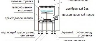
Schematic diagram of node No. 1
0 - safety valve 3 - automatic air vent 6 - three-way mixing valve 8 - balancing valve The coolant heated in the boiler passes through steel pipes with a diameter of 25 mm for boilers S40, S20, S10, S7. Air is removed from the boiler through an automatic air vent (3). A safety valve of 1.5 atmospheres is installed on the external circuit of the boiler. Through the valve, the heated coolant enters the nearest radiator (2) which, in the event of a power failure, can operate as a gravity radiator. The additional radiator (2) must be connected independently. It is necessary to prevent overheating of the boiler when the circulation pump is turned off. The radiator system (1) is connected at the top of the small circuit through a valve with a diameter of 25 mm. The return line of the radiators is fed to the circulation pump through a valve with a diameter of 25 mm. The heated coolant from the boiler enters the heating system manifold and then into the radiator system (1). The cooled coolant flows from the return manifold to the circulation pump (5). (8) - a balancing valve with the ability to adjust the flow through, with the help of which the flow from the circulation pump is distributed so that it is sufficient to heat the radiators, and at the same time, so that it is sufficient for the boiler itself. The total flow volume depends on the circulation pump and can also be changed by switching the pump speed settings. A three-way mixing valve (6) is connected to the circulation pump to the common return line. The mixing valve (6) is necessary for mixing the return and supply coolant to prevent the formation of condensation and is necessary for adjusting the temperature regime of the boiler. A circulation pump with a power of: for a 10 kW boiler 25–60 W for a 20 kW boiler 40–80 W for a 40 kW boiler 50–100 W is sufficient. RECOMMENDED BOILER WIRING DIAGRAM WITH A BOILER CONNECTION, WITHOUT HEATED FLOOR Schematic diagram of unit No. 2 0 - safety valve 1 — automatic air vent 7 — three-way mixing valve 8 — balancing valve The coolant heated in the boiler passes through steel pipes with a diameter of 25 mm for boilers S40, S20, S10, S7. Air is removed from the boiler through an automatic air vent (1). A safety valve of 1.5 atmospheres is installed on the external circuit of the boiler. The coolant is directed along the external circuit through the valve to the hot water boiler (3). After heating the boiler, the coolant flows back into the outer circuit of the piping unit. After the boiler (3), a selection is made to an additional radiator (4) which, in the event of a power failure, can operate as a gravity-fed one. The additional radiator (4) must be connected independently. It is necessary to prevent the boiler from overheating when the circulation pump (6) is turned off. The radiator system (5) is connected at the top of the small circuit through a valve with a diameter of 25 mm. The return line of the radiators is fed to the circulation pump through a valve with a diameter of 25 mm. The heated coolant from the boiler enters the heating system manifold and then into the radiator system (5). The cooled coolant flows from the return manifold to the circulation pump (6). The return coolant after the pump (6) is supplied to a three-way mixing valve (7). The mixing valve (7) is necessary for mixing the coolant in the return and supply lines to prevent the formation of condensation and is necessary for adjusting the temperature regime of the boiler. In the lower part of the circuit, after the mixing valve, a balancing valve (8) is installed with the ability to adjust the passing flow, with the help of which the flow from the circulation pump is distributed so that it is enough to heat the radiators, and at the same time, so that it is sufficient for the boiler In the return line after the balancing valve, drain valves are installed to recharge and empty the system, as well as an expansion tank (9). The pressure in the expansion tank should be 0.5-0.7 atmospheres. If necessary, an electric boiler can be installed instead of a boiler. A circulation pump with the following power is sufficient: for a 10 kW boiler 25–60 W for a 20 kW boiler 40–80 W for a 40 kW boiler 50–100 W RECOMMENDED BOILER PIRATION DIAGRAM WITH CONNECTION OF A BOILER AND HEATED FLOOR Schematic diagram of unit No. 3 1 — safety valve 2 — automatic air vent 9 - three-way separation valve 10 - circulation pump 11 - three-way mixing valve 12 - balancing valve The coolant heated in the boiler passes through steel pipes with a diameter of 25 mm for boilers S40, S20, S10, S7. Air is removed from the boiler through an automatic air vent (2). A safety valve of 1.5 atmospheres is installed on the external circuit of the boiler. The coolant is directed along the external circuit through the valve to the hot water boiler (5). After heating the boiler, the coolant flows back into the outer circuit of the piping unit. After the boiler (5), a selection is made to an additional radiator (6) which, in the event of a power failure, can operate as a gravity-fed one. The additional radiator (6) must be connected independently. It is necessary to prevent the boiler from overheating when the circulation pump (8) is turned off. The radiator system (4) is connected at the top of the small circuit through a valve with a diameter of 25 mm. The return line of the radiators is fed to the circulation pump through a valve with a diameter of 25 mm. The heated coolant from the boiler enters the heating system manifold and then into the radiator system (6). The cooled coolant flows from the return manifold to the circulation pump (8). The coolant is supplied to the underfloor heating pipe system by a pump (8). The coolant of the return line of heated floors is supplied to the mixing valve (9) necessary for mixing the supply and return lines and bringing the supply line to 30-37 degrees. (WITH). The return coolant after the pump (10) is supplied to a three-way mixing valve (11). The mixing valve (11) is necessary for mixing the coolant in the return and supply lines to prevent the formation of condensation and is necessary for adjusting the temperature regime of the boiler. In the lower part of the circuit, after the mixing valve (11), a balancing valve (12) is installed with the ability to adjust the passing flow, with the help of which the flow from the circulation pump is distributed so that it is enough to heat the radiators, and at the same time, so that it is sufficient for the boiler itself. In the return line after the balancing valve, drain valves are installed to recharge and empty the system, as well as an expansion tank (13). The pressure in the expansion tank should be 0.5-0.7 atmospheres. If necessary, an electric boiler can be installed instead of a boiler. A circulation pump with the following power is sufficient: for a 10 kW boiler 25–60 W for a 20 kW boiler 40–80 W for a 40 kW boiler 50–100 W
stropuva.com.by
Options for connecting the boiler to heating system lines
Connecting gas boilers
When it comes to gas heating boilers, it is possible to implement their connection to CO in several ways.
a. Direct connection of a gas boiler
Most often used in simple RMs. This assumes that the boiler has all the equipment necessary for this (safety group, expansion tank, circulation pump).
b. Connecting a gas boiler through a hydraulic separator
If you plan to install a complex heating system in your home, including low-temperature (warm water floors) and high-temperature (radiator) elements, then it is necessary to eliminate the “mismatch” in the movement of the coolant that occurs during operation. To do this, a hydraulic separator must be included in the piping, which performs the necessary hydraulic isolation. In fact, two coolant movement circuits are formed in the CO: the boiler circuit and the general CO circuit. Each of them has its own central control center. c. With additional heat exchanger
Installation of said element ensures waterproofing of said heating circuits from each other. The need for such a solution is due to:
- • use of different types of coolant (antifreeze and water) in circuits;
- • when combining closed and open systems within a single SO. Each of the circuits is equipped with its own central pump, make-up and drain taps, and safety groups.
d. Connecting a gas boiler using indirect heating boilers
The presence of the mentioned element in the CO allows you to constantly have a certain supply of hot water in the house, which is heated by the heat taken from the coolant operating in the CO. As a rule, these boilers are connected through special priority valves (three-way). If the house is large and the CO is multi-circuit, then this boiler is connected after the hydraulic separator.
Connecting solid fuel boilers
A specific feature of the mentioned types of boilers is their lack of a heat supply control function. It is impossible to interrupt the combustion of fuel. This, in the event of a power failure and the central heating unit stopping, can lead to the fact that continued heating will cause an increase in pressure in the lines, which can damage the CO.
To eliminate such a situation, several options for emergency schemes are being implemented to dump excess heat:
- • Connecting pumps to the battery;
- • Prompt supply of cold coolant (water);
- • The presence of a circuit operating in the mode of gravitational circulation of the coolant;
- • Connection of an optional emergency circuit.
Double-circuit solid fuel boilers are not recommended to be used in conjunction with gravity circulation systems.
Connecting electric boilers
If the boiler is an electrode model, then it is required in the heating circuit. Install: pressure gauge, air vent, non-return safety valve.
If the system is open, then in the pipeline, immediately behind the expansion tank. It is necessary to install shut-off valves.
Stropuva boiler or Bubafonya stove
List of structural elements of the Stropuva boiler.
In the previous article we talked about long-burning stoves for homes, cottages, bathhouses, and how to heat them. Today we will talk about two units that are similar in their principle of operation - the Lithuanian boiler Stropuva and the Bubafonya from Kolyma, and we will even try to compare them. Those who think whether it is possible to make a Stropuv boiler with their own hands will have to be disappointed, most likely this will not be possible.
Some structural elements are very complex and can only be manufactured in production conditions using machine tools. But a domestic, simplified analogue can be assembled in a day. Of course, it does not have such high characteristics as factory units, however, it will heat a dacha or garage in no time. The option is super economical and practical, like the AK-47.
Boiler design Stropuva
To answer the question of whether it is possible to make a Stropuva cauldron with your own hands, you must first honestly determine the degree of your skill. If you are a jack-of-all-trades with a lot of ingenuity, then the process may be within your power. If you are a homemade DIYer, then most likely there will be no point, because the task is really not an easy one. To see this, let’s look at the design of the Stropuva boiler. It consists of the following main structural elements:
- double body;
- telescopic air duct;
- air distributor;
- automatic air supply control system.
Of course, long-burning boilers in Stropuv are equipped with doors and pipes for supply and return coolant. There will be no difficulties with simple elements, but it is simply impossible to make basic ones at home. Let's start with a telescopic pipe, how to make it yourself? This is unrealistic without factory equipment. In principle, we can end this here; the attempt failed. Hypothetically, let's say that you managed to make a telescopic duct that can be folded by pulling a cord.
Surely you have identified the ring on the string in the long-burning boilers of Stropuvo. It is designed to lift the air supply pipe.
The layout of the unit is really complex. You need to do the following:
- connect two pipes of different diameters;
- cut in pipes for supply and return coolant in the outer pipe;
- attach a chamber for heating the air in the inner pipe from above (exactly in the middle);
- in the chamber from below, fix an already manufactured telescopic air duct with an air distributor at the end;
- You should also make a pipe to remove smoke from the inner pipe;
- install doors;
- install an air supply control system.
In this case, everything should be as airtight as possible. Can you cope with such a difficult task? Most likely not. So Mr. Afanasy Budyakin from Kolyma thought that this task was impossible, so he came up with an analogue of the Stropuva boiler. He didn’t call him anything, but simply posted it online under the nickname “bybafonja.” That’s how the name “Bubafonya” stuck to the domestic long-burning stove. We'll tell you about it a little later.
Before choosing a convector heater for your home, calculate the required power.
What is the best quality heater for your home? The answer is here.
Operating principle of the Stropuva boiler
Once the flame is sufficiently hot, it will burn from top to bottom.
Both the original and the analogue of the Stropuva boiler work on the same principle. First you need to load the firebox with bitters. Let us immediately make a reservation that this can only be done after the boiler has completely burned the previous fuel supply, since the source of smoldering must be at the top. To start the boiler you need:
- pull the ring and lift the telescopic air duct;
- remove ash through the bottom door (1-2 times a week);
- fill the firebox with wood or coal, depending on the model of the unit (there are wood-burning and universal ones);
- Set fire to paper or cloth soaked in gasoline on top;
- lower the air duct and close the doors.
From one load of firewood the boiler works for a little more than a day, from a briquette - up to two days, and on coal - for five whole days.
As the fuel burns out, the air distributor moves down until it reaches the bottom. The air supply is controlled by a bimetallic plate. The developers have increased the efficiency due to the fact that an air heating chamber is built into the Stropuva boiler design. The latter enters the furnace at a temperature of about 400 degrees. At this temperature, pyrolysis gases ignite. But, unfortunately, the plate loses its properties and every month you need to make adjustments to the settings, and after a year, completely replace it with a new one.
Due to the fact that the air is supplied in doses, it is possible to avoid temperature surges that occur during the operation of ordinary solid fuel boilers. Therefore, the Stropuva boiler piping scheme does without a storage tank, the so-called heat accumulator for the heating system.
Modern autonomous heaters for the home are energy-saving units with high efficiency.
Infrared lamp heaters for the home, unlike lamp TVs, are the latest heating equipment. Here you will find both types and characteristics.
Stropuva boiler connection diagram
Piping diagram with backup heater, hot water boiler and heated floor.
After the purchase, when filling out the documents, the seller will ask you: “Do you need the help of a specialist in installing the heater?” Do not rush to answer: “No.” The connection diagram for the Stropuva boiler is somewhat different from other types of solid fuel boilers. On the official website you can find three strapping options:
- with backup heater, hot water boiler and underfloor heating system;
- only with boiler;
- with a boiler and low-temperature underfloor heating system.
Maybe for some it is, as they say, “a piece of cake,” but for a person without specialized knowledge, these schemes cause stupor. This is not to mention connecting the Stropuva heating boiler yourself. In general, it is better to use the services of experts in this matter. By the way, opinions have been heard more than once on the forums about the complexity of tying this equipment.
Bubafonya stove with water jacket
Pyrolysis furnace Bubafonya from a gas cylinder with a water jacket.
Finally, we got to the domestic analogue of the Stropuva boiler, which is much simpler to implement, since it has a non-folding pipe for supplying air to the firebox. There are already so many instructions on how to make a Bubafonya stove with your own hands that only a blind person would not have seen them, unless, of course, they were interested in this topic. And why all? Yes, because the process is so simple and if you take the matter seriously, you can get a finished product from scratch in a day. What is the Bubafonya stove made from with your own hands:
- from a gas cylinder;
- from a barrel;
- from pipes
It can be either round or square. Let’s not repeat the same thing, just read the article: “Bubafonya stove from a gas cylinder” - and everything will become clear to you. Today we will consider a version of the product with a water circuit, as if we will try to repeat the principle of operation of the Stropuva boiler. All that is required is to make a simple Bubafonya and insert it into a pipe of a larger diameter. Thus, we obtain a gap in which the coolant will be heated.
Naturally, this space above and below is sealed so that various debris does not get there. What is important when making a Bubafonya stove with a water jacket with your own hands:
- use of heat-resistant steel;
- wall thickness of at least 4 mm;
- the presence of a tap for draining and replenishing water.
Immediately provide a hole in the upper part through the outer and inner walls for installing a chimney into it. There should also be enough space for water. The distance from the outer to the inner wall is about 10 cm. When connecting, do not confuse the supply and return pipes (supply from above).
Comparison of the Stropuva boiler and the Bubafonya stove
We will begin our analysis with the scope of application. If we are talking about a residential building, the Stropuva boiler definitely has the advantage. The characteristics of this unit allow it to work for a long time on one load, it is stable and reliable. At least, cases of complete failure have not yet been encountered. The operating principle of the Stropuva boiler allows you to connect to it both high-temperature heating and a hot water supply system with heated floors. Bubafonya cannot boast of this.
It is more suitable for heating greenhouses, garages, or, at most, summer houses. For more serious projects it is simply not applicable. Advantages of the Stropuva boiler design:
- continuous operation on coal for 5 days;
- temperature stability;
- ease of fuel loading compared to Bubafone.
There are also disadvantages, such as the complexity of the piping, the need for a separate room and the impossibility of repairs until a complete stop. It is also impossible to add fuel while the stove is operating and therefore you have to relight it every time you reload the firebox. But at the same time, of the two units being compared, only the Stropuva factory furnace is still suitable for serious projects. But Afanasy Budyakin’s invention is excellent for utility rooms, since the Bubafonya stove can be made quickly and inexpensively, which in this case is of decisive importance.
utepleniedoma.com