How to protect a solid fuel boiler from overheating and condensation
When purchasing and installing a solid fuel boiler, it is necessary to take into account the peculiarities of its operation, namely the high probability of overheating in emergency situations, which can result in a serious accident and even destruction of the water jacket of the unit (explosion). Also, considerable harm can be caused by the formation of condensation on the walls of the combustion chamber, which happens under certain operating conditions. To eliminate such troubles, the solid fuel boiler must be protected from overheating and condensation, which will be discussed in our article.
The basic principle of protecting the boiler from condensation
To protect a solid fuel boiler from the formation of condensation, it is necessary to eliminate the situation in which this process is possible. To do this, do not allow cold coolant to enter the boiler. The return temperature should be 20 degrees less than the supply temperature. In this case, the supply temperature must be at least 60 C.
The simplest method is to heat a small amount of coolant in the boiler to the nominal temperature, create a small heating circuit for its movement and gradually add the rest of the cold coolant to the hot water.
The idea is simple, but it can be implemented in various ways. For example, some manufacturers offer to purchase a ready-made mixing unit, the cost of which can be 25,000 rubles or more. For example, the FAR company (Italy) offers similar equipment for 28,500 rubles, and the Laddomat company sells a mixing unit for 25,500 rubles.
A more economical, but no less effective way to protect a solid fuel boiler from condensation is to regulate the temperature of the coolant supplied to the boiler using a thermostatic valve with a thermal head.
Causes of problems
Boiling of the coolant in systems with solid fuel boilers occurs for the following reasons:
- an air damper that controls the chain traction regulator is not completely closed;
- fluctuations in the supply of electrical energy;
- ECU malfunction, due to which the discharge regulator is turned off;
- a malfunction of the mechanical thermostat, due to which the air supply door may not close.
Condensation in the system occurs for other reasons. The water in the heating system is initially at room temperature. When the boiler is ignited, the latter rises locally and sharply, causing condensation to occur. It mixes with smoke and settles on the inner surface of the boiler. The crust formed when the walls are regularly “enveloped” in a mixture of smoke and condensation can be so thick that modern anti-corrosion agents will not help.
You can avoid boiler overheating. To completely eliminate the appearance of condensation - no, only to significantly minimize it. Let's look at how solid fuel boilers are protected from overheating.
What is the difference between heating flow and return?
And so, let’s summarize the differences between supply and return in heating:
- Supply – coolant that flows through water pipes from a heat source. This could be an individual boiler or central heating of the house.
- Return water is water that, having passed through all the heating radiators, goes back to the heat source. Therefore, at the input of the system there is supply, and at the output there is return.
- It also differs in temperature. The feed is hotter than the return.
- Installation method. The water conduit that is attached to the top of the battery is the supply; the one that connects to the bottom is the return line.
The efficient operation of the heating system determines how comfortable the temperature in the house will be during the cold season. Sometimes situations arise when hot water is supplied to the system, but the batteries remain cold. It is important to find the cause and eliminate it. To solve the problem, you need to know the design of the heating system and the reasons for cold return during hot supply.
Protection of solid fuel boilers with buffer tank
Protecting the boiler using gravity flow is a rational and correct option for protecting the boiler, in my opinion. I rarely make gravity flow systems. They look disgusting. Large diameter pipes on the walls, brrr...
Previously, they did this out of despair, but in a new house, making a gravity-flow system is stupid. There are people who periodically scold me for being against gravity systems.
Guys! I have seen many times how gravity systems are dismantled and a modern heating system is made. But I have never seen anyone break modern heating and make it flow by gravity.
With a solid fuel boiler, it is wise to install a buffer tank. Or a heat accumulator, whatever you prefer to call it.
In this case, the boiler with the buffer must be connected so that there is gravity flow. In this case, during a power outage, the coolant will circulate from the boiler to the buffer tank. The boiler will not boil.
Another plus to installing a buffer tank is the ability to regulate the temperature in the house. I tie the thermostat to the circulation pump of the heating circuit. In this case, my circulation pump turns on according to the air temperature in the house.
In the video, Sasha explains in detail how we make heating systems in private homes with solid fuel boilers.
If there is no buffer tank, then you can install a heating radiator connected to the boiler so that there is gravity flow. It is believed that such a radiator protects the boiler from boiling when the circulation pump is turned off.
How to choose the volume of the buffer tank
I select the volume of the buffer tank at the rate of 40 liters per kilowatt of boiler power. In this case, the volume of the buffer tank cannot be less than a ton.
That is, if the power of a solid fuel boiler is less than or equal to 25 kW, then I set a buffer per ton. If the boiler is more powerful, then I calculate it at the rate of 40 liters per kilowatt.
How to choose a buffer tank
If people asked for cheaper ones, I recommended S-Tank buffer tanks. Then I saw how they were leaking from people. I saw how the manufacturer reacted to this and stopped recommending them to people. On the contrary, I even discourage you from buying it.
The guys installed an S-TANK buffer tank and got stuck for 425 thousand rubles
Now I use TESY, HAJDU, DRAZICE from cheap buffer containers. I have budget orders, so I very rarely install good and expensive tanks. You can safely buy ACV, VIESSMANN, WOLF tanks.
Heat meters
Let us remember once again that the heat supply network of an apartment building is equipped with thermal energy metering units, which record both the gigacalories consumed and the cubic capacity of water passed through the intra-house line.
In order not to be surprised by bills containing unrealistic amounts for heat when the degrees in the apartment are below normal, before the start of the heating season, check with the management company whether the meter is in working condition and whether the verification schedule has been violated.
Can water in a well freeze? No, the water will not freeze, because... In both sandy and artesian wells, the water is below the freezing point of the soil. Is it possible to install a pipe with a diameter greater than 133 mm in a sand well in a water supply system (I have a pump for a large pipe)? When installing a sand well, it does not make sense to install a pipe with a larger diameter, because Sand well productivity is low. The Malysh pump is specially designed for such wells. Can a steel pipe in a water supply well rust? Quite slowly. Since when constructing a country water supply well it is sealed, there is no oxygen access to the well and the oxidation process is very slow. What are the pipe diameters for an individual well? What is the productivity of a well at different pipe diameters? Pipe diameters for constructing a water well: 114 - 133 (mm) - well productivity 1 - 3 cubic meters per hour; 127 - 159 (mm) - well productivity 1 - 5 cubic meters ./hour; 168 (mm) - well productivity 3 - 10 cubic meters/hour; REMEMBER! It is necessary that...
After installing the heating system, it is necessary to adjust the temperature regime. This procedure must be carried out in accordance with existing standards.
Requirements for coolant temperature are set out in regulatory documents that establish the design, installation and use of engineering systems of residential and public buildings. They are described in the State Building Codes and Rules:
- DBN (V. 2.5-39 Heat networks);
- SNiP 2.04.05 “Heating, ventilation and air conditioning.”
For the calculated supply water temperature, the figure is taken that is equal to the water temperature at the outlet of the boiler, according to its passport data.
For individual heating, deciding what the coolant temperature should be should take into account the following factors:
- The beginning and end of the heating season based on the average daily outdoor temperature of +8 °C for 3 days;
- The average temperature inside heated premises of housing, communal and public importance should be 20 °C, and for industrial buildings 16 °C;
- The average design temperature must comply with the requirements of DBN V.2.2-10, DBN V.2.2.-4, DSanPiN 5.5.2.008, SP No. 3231-85.
According to SNiP 2.04.05 “Heating, ventilation and air conditioning” (clause 3.20), the coolant limit values are as follows:
Depending on external factors, the water temperature in the heating system can be from 30 to 90 °C. When heated above 90 °C, dust and paintwork begin to decompose. For these reasons, sanitary standards prohibit greater heating.
To calculate optimal indicators, special graphs and tables can be used, which define standards depending on the season:
- With an average reading outside the window of 0 °C, the supply for radiators with different wiring is set at 40 to 45 °C, and the return temperature at 35 to 38 °C;
- At -20 °C, the supply is heated from 67 to 77 °C, and the return rate should be from 53 to 55 °C;
- At -40 °C outside the window, all heating devices are set to the maximum permissible values. On the supply side it is from 95 to 105 °C, and on the return side it is 70 °C.
Installation of a boiler room, connection of a boiler - do not make mistakes
Installing a boiler room yourself is both interesting and profitable. But when connecting the boiler and arranging the boiler room, shortcomings always appear. Some have a very significant effect on the performance of the heating system. Others only spoil aesthetics.
In order not to inherit the circumstances that happened to one good person, who, in a deep frost, knee-deep in icy water, with plumbing keys out of balance, tried something...
It is better to try to install and connect the boiler according to the rules, to equip the boiler room with the least possible defects. Otherwise, it will not work, or it will constantly “ruin life” and require rework.
In most cases, when creating a boiler room and connecting the boiler with your own hands, polypropylene is used. It is very easy to install using low-temperature welding, and it is extremely cheap. But its main drawback is the complete lack of guarantee for the quality of installation and the inability to check the quality of joints. What needs to be done to equip the boiler room correctly - read below.
A filter in the system is required
A common but serious mistake is that the system does not have a dirt filter. The coolant must enter the boiler from the return through a filter. If sediment or particles get into the heat exchanger, it sinteres there, changing the characteristics of the boiler and rendering it unusable. A small detail is a filter that cannot be skimped on.
It is better not to use polypropylene taps
Polypropylene taps are cheap, but often leak and are not reliable. It’s better to use regular metal ones. But if you want to save money, or the tap will not be used often, then a polypropylene tap needs to be installed (welded) with a sufficient supply of pipes so that it can be cut out and another one welded.
The valve must not be placed directly on the fitting. Otherwise, you will have to cut out along with the fitting and half the system will still be lame.... If you solder right next to the collector, you will have to throw away the entire collector, for example. When installing soldered-in faucets, it is better to foresee in advance how it will be replaced. In the bottom photo, the system is many times more reliable because of the taps...
Position the boiler correctly
Any equipment in the boiler room must be located leaving the necessary clearances. so that there is enough space for its maintenance. The boiler must be at a sufficient distance from the wall and from the boiler, from any equipment, so that it can be conveniently serviced. The standard distance to the boiler from the finished floor surface is 145 cm, which corresponds to the height of the kitchen shelves.
Install expansion tanks and emergency valves
The liquid expands when heated, which is compensated by the compression of air in the expansion tank. More about expansion tanks
It is important not to forget to install an expansion tank and an emergency valve, not only in the heating system, but also in the secondary loop of the boiler - for the hot water supply. Otherwise, an accident is possible, something will break.
A simple boiler room diagram is better
A circuit with the same functions and similar reliability can be assembled with a significant difference in price. For example.
For a house with an area of 200 square meters, with an indirect heating boiler with automated boilers that operate only alternately (gas and backup electric), with radiator and floor systems, the boiler room is assembled even without a single pump and mixing unit.
Simply, boilers with shut-off valves and filters on the return lines are connected to tees, and then from the supply and return there are branches for 3 consumers - a boiler, a heated floor, radiators.
LiveInternetLiveInternet
Quote from ITDalee
Read in full In your quotation book or community!
Unlike electric and gas heating units, solid fuel boilers are almost never equipped with circulation pumps, a safety group, or adjustment and control devices. Everyone solves these issues independently, choosing a heating device piping scheme in accordance with the type and features of the heating system. Not only the efficiency and performance of heating, but also its reliable, trouble-free operation depends on how correctly the heat generator is installed. That is why it is important to include in the diagram components and devices that will ensure the durability of the heating unit and its protection in the event of emergency situations. In addition, when installing a solid fuel boiler, you should not give up equipment that creates additional convenience and comfort. Using a heat accumulator, you can solve the problem of temperature differences when rebooting the boiler, and an indirect heating boiler will provide the house with hot water. Have you thought about connecting a solid fuel heating unit according to all the rules? We will help you with this!
Typical wiring diagrams for solid fuel boilers
The complexity of controlling the combustion process in solid fuel boilers leads to high inertia of the heating system, which negatively affects the convenience and safety during operation. The situation is further complicated by the fact that the efficiency of units of this type directly depends on the temperature of the coolant. For efficient heating operation, the piping must ensure the temperature of the thermal agent is within 60 - 65 ° C. Of course, if the equipment is not integrated correctly, such heating at above-zero temperatures “overboard” will be very uncomfortable and uneconomical. In addition, the full operation of the heat generator depends on a number of additional factors - the type of heating system, the number of circuits, the presence of additional energy consumers, etc. The wiring diagrams presented below take into account the most common cases. If none of them meets your requirements, then knowledge of the principles and structural features of heating systems will help in developing an individual project.
Open type system with natural circulation in a private house First of all, it should be noted that open gravity type systems are considered the most suitable for solid fuel boilers. This is due to the fact that even in emergency cases associated with a sharp increase in temperature and pressure, the heating will most likely remain sealed and operational. It is also important that the functionality of the heating equipment does not depend on the availability of power. Considering that wood-burning boilers are installed not in megacities, but in areas remote from the benefits of civilization, this factor will not seem so insignificant to you. Of course, this scheme is not without its drawbacks, the main ones being:
- free access of oxygen to the system, which causes internal corrosion of pipes;
- the need to replenish the coolant level due to its evaporation;
- uneven temperature of the thermal agent at the beginning and end of each circuit.
A layer of any mineral oil 1–2 cm thick, poured into the expansion tank, will prevent oxygen from entering the coolant and reduce the rate of evaporation of the liquid. Despite its shortcomings, the gravity scheme is very popular due to its simplicity, reliability and low cost.
When deciding to install using this method, keep in mind that for normal coolant circulation, the boiler inlet must be at least 0.5 m below the heating radiators. The supply and return pipes must have slopes for normal coolant circulation. In addition, it is important to correctly calculate the hydrodynamic resistance of all branches of the system, and during the design process try to reduce the number of shut-off and control valves. The correct operation of the system with natural coolant circulation also depends on the installation location of the expansion tank - it must be connected at the highest point.
Closed system with natural circulation
Installing a membrane-type expansion tank on the return line will avoid the harmful effects of oxygen and eliminate the need to control the coolant level. When deciding to equip a gravity system with a sealed expansion tank, consider the following points:
- the capacity of the membrane tank must contain at least 10% of the volume of the entire coolant;
- a safety valve must be installed on the supply pipe;
- the highest point of the system must be equipped with an air vent.
Additional devices that are included in the boiler safety group (safety valve and air vent) will have to be purchased separately - manufacturers very rarely equip units with such devices. The safety valve allows the coolant to be discharged if the pressure in the system exceeds a critical value. A normal operating indicator is considered to be a pressure of 1.5 to 2 atm. The emergency valve is set to 3 atm.
Features of systems with forced coolant movement
In order to equalize the temperature in all areas, a circulation pump is integrated into the closed heating system. Since this unit can provide forced movement of the coolant, the requirements for the level of installation of the boiler and compliance with slopes become negligible. However, you should not give up the autonomy of natural heating. If a bypass branch, called a bypass, is installed at the boiler outlet, then in the event of a power outage, the circulation of the thermal agent will be ensured by gravitational forces.
The electric pump is installed on the return line, between the expansion tank and the inlet fitting. Thanks to the lower coolant temperature, the pump operates in a more gentle mode, which increases its durability. Installing a circulation unit on the return line is also necessary for safety reasons. When water boils in the boiler, steam may form, the entry of which into the centrifugal pump can completely stop the movement of the liquid, which can lead to an accident. If the device is installed at the inlet of the heat generator, it will be able to circulate the coolant even in the event of emergency situations.
Connection via manifolds
If it is necessary to connect several parallel branches with radiators, a water heated floor, etc. to a solid fuel boiler, then balancing of the circuits is required, otherwise the coolant will follow the path of least resistance, and the remaining parts of the system will remain cold. For this purpose, one or more collectors (combs) are installed at the outlet of the heating unit - distribution devices with one input and several outputs. Installation of combs opens up wide possibilities for connecting several circulation pumps, allows you to supply a thermal agent of the same temperature to consumers and regulate its supply. The only disadvantage of this type of piping can be considered the complication of the design and the increased cost of the heating system.
A separate case of manifold piping is a connection with a hydraulic arrow. Its difference from a conventional collector is that this device acts as a kind of intermediary between the heating boiler and consumers. Made in the form of a large-diameter pipe, the hydraulic arrow is installed vertically and connected to the inlet and pressure pipes of the boiler. In this case, consumers are inserted at different heights, which allows you to select the optimal temperature for each circuit.
Installation of emergency and control systems
Emergency and control systems serve several purposes:
- protection of the system from depressurization in the event of an uncontrolled increase in pressure;
- temperature control of individual circuits;
- boiler protection from overheating;
- prevention of condensation processes associated with large differences in supply and return temperatures.
To solve system safety problems, a safety valve, emergency heat exchanger or natural circulation circuit is introduced into the piping circuit. As for the issues of regulating the temperature of the thermal agent, thermostatic and controlled valves are used for these purposes.
Trim with three-way valve.
A solid fuel boiler is a periodic heating unit, so it is at risk of corrosion due to condensation that falls on its walls during heating. This is due to the ingress of too cold coolant from the return into the heat exchanger of the heating unit. The danger of this factor can be eliminated using a three-way valve. This device is an adjustable valve with two inputs and one output. Based on a signal from the temperature sensor, the three-way valve opens the hot coolant supply channel to the boiler inlet, preventing the formation of a dew point. As soon as the heating unit enters operating mode, the supply of liquid in a small circle stops.
A fairly common mistake is to install a centrifugal pump before a three-way valve. Naturally, with the valve closed, there can be no talk of any liquid circulation in the system. It is correct to install the pump after the adjusting device. A three-way valve can also be used to regulate the temperature of the heating agent supplied to consumers. In this case, the device is set to work in the other direction, mixing cold coolant from the return to the supply.
Circuit with buffer capacity
The low controllability of solid fuel boilers requires constant monitoring of the amount of firewood and draft, which significantly reduces the convenience of their operation. Installing a buffer tank (heat accumulator) will allow you to load more fuel without worrying about possible boiling of the liquid. This device is a sealed tank that separates the heating unit from consumers. Due to its large volume, the buffer tank can accumulate excess heat and transfer it to radiators as needed. The mixing unit, which uses the same three-way valve, will help regulate the temperature of the liquid coming from the heat accumulator.
Trim elements ensuring the safety of the heating system
In addition to the safety valve mentioned above, protecting the heating unit from overheating is achieved using an emergency circuit through which cold water from the water supply is supplied to the heat exchanger. Depending on the design of the boiler, the coolant can be supplied directly to the heat exchanger or to a special coil installed in the working chamber of the unit. By the way, it is the last option that is the only possible one for systems with filled antifreeze. The water supply is carried out using a three-way valve, which is controlled by a sensor installed inside the heat exchanger. The “waste” liquid is discharged through a special pipeline connected to the sewer system.
Connection diagram for an indirect heating boiler
Piping with connection of a boiler for hot water supply can be used for heating systems of all types. To do this, a special heat-insulated container (boiler) is connected to the water supply and hot water supply system, and a coil is installed inside the water heater, which is cut into the heating agent supply line. Passing through this circuit, the hot coolant transfers heat to the water. Often, an indirect heating boiler is also equipped with heating elements, thanks to which it becomes possible to obtain hot water in the warm season.
Correct installation of a solid fuel boiler in a closed heating system
A huge advantage of solid fuel boilers is that their installation does not require any permits. It is quite possible to carry out the installation yourself, especially since this does not require any special tools or special knowledge. The main thing is to approach the work responsibly and follow the order of all stages.
Boiler room installation. The disadvantage of heating units used to burn wood and coal is the need for a special, well-ventilated room. Of course, it would be possible to install a boiler in the kitchen or bathroom, however, periodic emissions of smoke and soot, dirt from fuel and combustion products make this idea unsuitable for implementation. In addition, installing burning equipment in living rooms is also unsafe - the release of fumes can lead to tragedy. When installing a heat generator in a boiler room, several rules are followed:
- the distance from the combustion door to the wall must be at least 1 m;
- ventilation ducts must be installed at a distance no higher than 50 cm from the floor and no lower than 40 cm from the ceiling;
- There should be no fuel, lubricants or flammable substances and objects in the room;
- The base area in front of the ash pit is protected with a metal sheet measuring at least 0.5 x 0.7 m.
In addition, at the location where the boiler is installed, an opening is provided for the chimney, which is led outside. Manufacturers indicate the configuration and dimensions of the chimney in the technical data sheet, so there is no need to invent anything. Of course, if the need arises, you can deviate from the documentation requirements, but in any case, the channel for removing combustion products must provide excellent traction in any weather. When installing a chimney, all connections and cracks are sealed with sealing materials, and windows are also provided for cleaning the channels from soot and a condensate catcher.
Preparing to install a heating unit
Before installing the boiler, select a piping scheme, calculate the length and diameter of the pipelines, the number of radiators, the type and quantity of additional equipment and shut-off and control valves. Despite all the variety of design solutions, experts recommend choosing combined heating, which can provide forced and natural circulation of the coolant. Therefore, when making calculations, it is necessary to consider how a parallel section of the supply pipeline (bypass) with a centrifugal pump will be installed and to provide for the slopes necessary for the operation of the gravity system. You shouldn’t give up on buffer capacity either. Of course, its installation will entail additional costs. However, a storage tank of this type will be able to level out the temperature curve, and one load of fuel will last for a longer time.
Particular comfort will be provided by a solid fuel boiler with an additional circuit, which is used for hot water supply. Considering the fact that due to the installation of a solid fuel unit in a separate room, the length of the hot water circuit increases significantly, an additional circulation pump is installed on it. This will eliminate the need to drain cold water while waiting for hot water to flow. Before installing the boiler, be sure to provide space for the expansion tank and not forget about devices designed to reduce pressure in the system in critical situations. A simple strapping diagram that can be used as a working design is shown in our drawing. It combines all the equipment discussed above and ensures its correct and trouble-free operation.
Installation and connection of a solid fuel heat generator
After carrying out all the necessary calculations and preparing the equipment and materials, installation begins.
- The heating unit is installed in place, leveled and secured, after which the chimney is connected to it.
- Heating radiators are mounted, a heat accumulator and an expansion tank are installed.
- Install the supply pipeline and bypass, on which the circulation pump is installed. Ball valves are installed in both sections (direct and bypass) so that the coolant can be transported by forced or natural means. We remind you that the centrifugal pump can only be installed with the correct orientation of the shaft, which must be in a horizontal plane. The manufacturer indicates diagrams of all possible installation options in the product instructions.
- The pressure line is connected to the heat accumulator. It must be said that both the inlet and outlet pipes of the buffer tank must be installed in its upper part. Thanks to this, the amount of warm water in the container will not affect the readiness of the heating circuit. We definitely note the fact that cooling the boiler during the reboot period will reduce the temperature in the system. This is due to the fact that at this time the heat generator will work as an air heat exchanger, transferring heat from the heating system to the chimney. To eliminate this shortcoming, separate circulation pumps are installed in the boiler and heating circuits. By placing a thermocouple in the combustion zone, you can stop the movement of coolant through the boiler circuit when the fire dies out.
- A safety valve and an air vent are installed on the supply line.
- Connect the emergency circuit of the boiler or install shut-off and control valves, which, when the water boils, will open the main line for its discharge into the sewer and the channel for supplying cold liquid from the water supply.
- Install a return pipeline from the heat accumulator to the heating unit. A circulation pump, a three-way valve and a settling filter are installed in front of the boiler inlet pipe.
- An expansion tank is mounted separately on the return pipeline. Note! Shut-off valves are not installed on pipelines that are connected to protection devices. These areas should have as few connections as possible.
- The upper outlet of the heat storage tank is connected to a three-way valve and the circulation pump of the heating circuit, after which the radiators are connected and the return pipeline is installed.
- After connecting the main circuits, they begin to install a hot water supply system. If the heat exchanger coil is built into the boiler, then it will be enough to simply connect the cold water inlet and the outlet to the “hot” line to the appropriate pipes. When installing a separate indirect heating water heater, use a circuit with an additional circulation pump or three-way valve. In both cases, a check valve is installed at the cold water supply inlet. It will block the path for heated liquid into the “cold” water supply.
- Some solid fuel boilers are equipped with a draft regulator, the function of which is to reduce the flow area of the blower. Due to this, the air flow into the combustion zone is reduced and its intensity, and, accordingly, the temperature of the coolant is reduced. If the heating unit has this design, then install and adjust the drive of the air damper mechanism.
The places of all threaded connections must be carefully sealed using plumbing flax and a special non-drying paste. After installation is completed, coolant is poured into the system, centrifugal pumps are turned on at full power and all connections are carefully inspected for leaks. After making sure that there are no leaks, fire up the boiler and check the operation of all circuits at maximum modes.
Features of integrating a solid fuel unit into an open heating system
The main feature of open heating systems is the contact of the coolant with atmospheric air, which occurs with the participation of an expansion tank. This container is designed to compensate for the thermal expansion of the coolant that occurs when it is heated. The expander is installed at the highest point of the system, and in order to prevent hot liquid from flooding the room when the tank is overfilled, a drain tube is connected to its upper part, the other end of which is discharged into the sewer.
The large volume of the tank forces it to be installed in the attic, so additional insulation of the expander and the pipes suitable for it will be required, otherwise they may freeze in winter. In addition, you must remember that this element is part of the heating system, so its heat losses will lead to a decrease in the temperature in the radiators. Since the open system is not sealed, there is no need to install a safety valve or connect emergency circuits. When the coolant boils, the pressure will be released through the expansion tank.
Special attention should be paid to pipelines. Since the water in them will flow by gravity, the circulation will be influenced by the diameter of the pipes and the hydraulic resistance in the system. The last factor depends on turns, narrowings, level changes, etc., so their number should be minimal. In order to initially impart the necessary potential energy to the water flow, a vertical riser is installed at the outlet of the boiler. The higher the water can rise along it, the higher the coolant speed will be and the faster the radiators will warm up. For the same purposes, the return inlet should be located at the lowest point of the heating system.
Finally, I would like to note that in open systems it is preferable to use water rather than antifreeze. This is due to higher viscosity, reduced heat capacity and rapid aging of the substance upon contact with air. As for the water, it is best to soften it and, if possible, never drain it. This will increase the service life of pipelines, radiators, heat generators and other heating equipment several times.
What is return in a heating system?
The return is a coolant located inside the heating system. During operation, it passes through all heating devices and gives off heat to them. Then, already cooled, the coolant returns to the boiler , where it is heated and begins a new cycle.
Photo 1. Heating diagram with a circulation pump and expansion tank. The arrows show the movement of the coolant.
water and antifreeze act as a coolant . It is put into operation either naturally (under the influence of gravity) or forcibly (using a pump).
How to make radiators hot - looking for solutions
If you find that the return is too cold, you should take a number of steps to find the causes and troubleshoot problems. First of all, you need to check that the connection is correct. If the connection is not made correctly, the down pipe will be hot when it should be slightly warm. The pipes should be connected according to the diagram.
To avoid air pockets that impede the flow of coolant, it is necessary to provide for the installation of a Mayevsky valve or bleeder for air removal. Before bleeding the air, you need to turn off the supply, open the tap and let out the air. Then the tap is turned off and the heating valves open.
Often the cause of cold return is the control valve: the cross-section is narrowed. In this case, the tap must be dismantled and the cross-section increased using a special tool. But it is better to buy a new faucet and replace it.
The reason may be clogged pipes. You need to check them for passability, remove dirt and deposits, and clean them well. If passability cannot be restored, the clogged areas should be replaced with new ones.
If the coolant flow rate is insufficient, you need to check whether there is a circulation pump and whether it meets the power requirements. If it is missing, it is advisable to install it, and if there is a lack of power, replace or upgrade it.
Knowing the reasons why heating may not work efficiently, you can independently identify and eliminate malfunctions. Comfort in the house during the cold season depends on the quality of heating. If you carry out the installation work yourself, you can save on hiring third-party labor.
In the article we will touch on problems related to pressure and diagnosed with a pressure gauge. We will structure it in the form of answers to frequently asked questions. Not only the difference between the supply and return in the elevator unit will be discussed, but also the pressure drop in a closed heating system, the operating principle of the expansion tank and much more.
Pressure is no less important heating parameter than temperature.
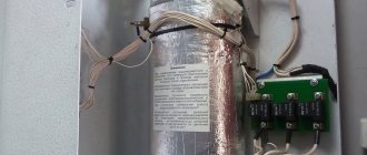
Insulation of fittings
Let's consider the issue of the need to insulate the fittings. Long pipe lengths, many fittings and high operating temperatures in the system lead to heat loss. At finished facilities, heating equipment that is not properly insulated overheats the surrounding space. In the room where the boiler and heat accumulator are installed, the temperature can reach plus 27 degrees in severe frost. Fuel is wasted and system efficiency decreases. After insulating the pipes, it is possible to gain a few degrees and reduce fuel consumption.
When insulating the fittings, you must remember that when working from the side of the boilers, the pipes become very hot, since they can transport water hotter than 100 degrees. Polyethylene foam insulation is not suitable in this case. It can only be installed in another part of the circuit on the side of the radiators of the heating system. In a boiler room, it is better to put rubber insulation that is more resistant to heat on hot pipes. It is also worth additionally insulating fittings and other fittings.
For safety reasons, it is not recommended to insulate pumps. This equipment is limited to exceed ambient temperature limits. If you insulate the pumps from the boiler side, you can insulate them too much, and this is unacceptable.
Why is the riser hot and the batteries cold?
Sometimes, with a hot supply, the return of the heating battery still remains cold. There are several main reasons for this:
- installation was performed incorrectly;
- the system or one of the risers of a separate radiator is airborne;
- insufficient fluid flow;
- the cross-section of the pipe through which the coolant is supplied has decreased;
- The heating circuit is dirty.
Cold return is a serious problem that must be eliminated. It entails many unpleasant consequences: the temperature in the room does not reach the desired level, the efficiency of radiators decreases, and there is no way to correct the situation with additional devices. As a result, the heating system does not work as it should.
The main trouble with cold return is the large temperature difference that occurs between the supply and return temperatures. In this case, condensation appears on the walls of the boiler, reacting with carbon dioxide, which is released during fuel combustion. As a result, acid is formed, which corrodes the walls of the boiler and shortens its service life.
Reasons that may result in overheating of a solid fuel boiler
Even at the selection and purchase stage, it is important to take into account the performance characteristics of the heating device. Many models that are on sale today have a built-in overheating protection system. Whether it works or not is the second question. However, it is necessary to adhere to certain knowledge and skills in order to create an effective and safe autonomous heating system at home.
The reliable operation of the heating unit depends on the operating conditions. In case of obvious violations of the technological parameters of heating equipment and abuse of standard safety rules, there is a high probability of an emergency situation.
For reference: exceeding the temperature in the combustion chamber of the permissible parameters can cause boiler water to boil. The result of an uncontrolled process is depressurization of the heating circuit and destruction of the heat exchanger housing. In the case of hot water boilers, an explosion may occur if overheated.
Possible negative consequences can be prevented even at the stage of installation of a solid fuel boiler. Proper wiring of the heating apparatus will be the key to your safety and reliable operation of the unit in the future.
If we talk in detail, then in each case the protection system of a solid fuel boiler has its own specifics and features. Each heating system has its pros and cons. Eg:
- When it comes to solid fuel boilers with natural coolant circulation, it is necessary to take care of the safety and performance of the heating equipment even during installation. The pipes in the system are metal. Moreover, the diameter of such pipes must exceed the diameter of the pipes used to lay the circuit with forced circulation of the coolant. Sensors installed on the water circuit will indicate possible overheating of the coolant. The safety valve and expansion tank play the role of a compensator, reducing excess pressure in the system.
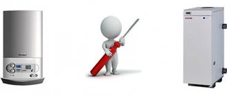
What are the ways to protect heating equipment from overheating?
*
In order to increase the consumer attractiveness of their products, manufacturing companies try to include any guarantees of their safety in the technical passport of boiler equipment. The uninitiated consumer has no idea about the means of protecting a heating boiler from boiling.
The following methods currently exist to ensure the protection of solid fuel units used for autonomous heating systems. The effectiveness of each method is explained by the operating conditions of boiler equipment and the design features of the units.
In most cases, in the technical data sheet for a heating device, manufacturers recommend using tap water for cooling. In some cases, solid fuel heating boilers are equipped with built-in additional heat exchangers. There are models of boilers with remote heat exchangers. A safety valve is used to prevent overheating. The safety valve is designed only to relieve excessive pressure in the system, while the safety valve allows access to tap water when the boiler overheats.
Important! In the presence of cast iron heating devices, such a measure is fundamentally incorrect. Cast iron heat exchangers are afraid of sudden temperature changes. Injecting cold water into the circuit may result in loss of integrity of the heat exchanger housing. (cast iron heated to a high temperature will simply burst upon contact with cold water).
Exceeding the temperature of the coolant above 100 0C creates excess pressure that opens the valve. Under the influence of tap water, which is supplied under pressure of 2-5 bar, hot water is forced out of the circuit by cold.
*
The first aspect that causes controversy about cooling with tap water is the lack of electricity to operate the pump. The expansion tank does not contain enough water to cool the boiler.
The second aspect that this cooling method rejects is related to the use of antifreeze as a coolant. If an emergency occurs, up to 150 liters of antifreeze will go into the sewer along with the incoming cold water. Is this method of protection worth it?
The presence of a UPS will allow you to maintain the operation of the circulating pump in a critical situation, with the help of which the coolant will evenly disperse through the pipeline without having time to overheat. As long as the battery capacity lasts, the uninterruptible power supply guarantees the operation of the pump. During this time, the boiler should not have time to heat up to critical parameters; the automation will work, running water through a spare, emergency circuit.
Another way to get out of a critical situation would be to install an emergency circuit in the piping of a solid fuel unit. Switching off the pump can be duplicated by the operation of a spare circuit with natural coolant circulation. The role of the emergency circuit is not to provide heating for residential premises, but only to be able to remove excess thermal energy in an emergency.
Note: the installation of an emergency circuit can be replaced by installing a bypass, which in extreme cases will divert overheated boiler water to an expansion tank or heat accumulator.
*
This scheme for organizing the protection of the heating unit from overheating is reliable, simple and easy to use. You will not need any special funds for its equipment and installation. The only conditions for such protection to work are:
- the presence of an expansion tank or storage tank in the system;
- use of a petal type check valve only;
- the secondary circuit pipes must be larger in diameter than the conventional heating circuit.
How to build a thermostatic valve
Thermostatic valves come in two types:
- mixing - flow A entering the valve is distributed into flow B and flow AB
- distribution - flow A entering the valve is distributed into 2 flows
The mixing valve is installed on the return line, and the distribution valve is installed on the supply line. The operation of the valve is controlled by a thermal head with a thermal flask.
The thermoflask is attached using a special sleeve to the surface of the return pipeline in close proximity to the heating boiler. Inside the flask there is a working fluid, the temperature of which is equal to the temperature of the coolant before entering the boiler. If the temperature of the coolant increases, the working fluid increases in volume, and, conversely, when the temperature of the coolant decreases, the volume of the working fluid decreases. Expanding or contracting, the working fluid presses on the rod, closing or opening the thermostatic valve.
Using a thermal head, you can set a certain temperature, above (below) which the coolant will not be heated. How to set the temperature by choosing the operating modes of the thermal head is described in detail in the instructions for it.
Another feature of the thermostatic valve is that it reduces the flow of coolant to the boiler, but never closes it or opens it completely, protecting the boiler from overheating and boiling. The valve is completely closed only when the boiler is started.
Application of safety valve
This is not the same as a safety valve. The latter simply relieves system pressure, but does not cool it. Another thing is the boiler overheating protection valve, which takes hot water from the system and in return supplies cold water from the water meter unit. The device is non-volatile and is attached to the supply and return lines, water supply and sewerage networks.
When the temperature of the coolant is more than 105? C, the valve opens and, thanks to the pressure in the water meter unit of 2-5 Bar, hot water is forced out of the jacket of the heat generator and pipelines with cold water, after which it goes into the sewer. How the protection valve for a solid fuel boiler is attached is shown in the diagram:
The disadvantage of this protection option is that it is not suitable for systems filled with antifreeze liquid. Moreover, the scheme is not applicable in conditions where there is no mechanized water supply, because when the electrical power is turned off, the water supply from underground using wells or a swimming pool will also stop.
Diagram of piping and connection of cast iron boilers - gas and solid fuel
Greetings, friends! In this article I will tell you how to properly tie and connect a cast iron boiler to the heating system so that it survives the first start-up.
And also about why sections of a new cast-iron boiler from a good manufacturer leak at the first start-up, the reasons for the breakdown of gas and solid-fuel cast-iron boilers. You will learn the wiring diagram for a buffer tank, a heat accumulator and an indirect heating boiler.
Let's look at the nuances and look at the diagram of the correct piping of a cast-iron boiler.
For all controversial technical issues, see the notes at the end of the article!
The standard installation of any boiler room includes:
- Pump
- expansion tank with water make-up group
- safety group that can be installed on the boiler
- instrumentation
- Distribution manifold
Installation of a boiler circuit mixing valve for cast iron boilers
Unfortunately, steel and alloys tend to expand when heated, which can lead to heat exchanger failure. And cast iron is one of the most fragile alloys.
When starting the boiler, the steel expands greatly when heated, and until the heating system is completely warmed up, cold water flows into the boiler from the return line
, and hot water leaves the boiler supply,
enormous mechanical stress on the heat exchanger, leading to leaks and cracks in boiler sections.
In solid fuel boilers , soot, tar, and condensate are intensively deposited on the cold heat exchanger and in the chimney when return water enters the boiler at a temperature below 50 degrees C, and in gas boilers - condensate from moisture from the burned gas inside the boiler. Low-temperature corrosion of steel is also present.
Therefore, a mechanical mixing valve , otherwise this thermomechanical circuit is called a “low-temperature corrosion protection unit,” since it is recommended to use it for steel boilers.
Installation diagram of the boiler circuit mixing valve and features of coolant circulation in it to protect the boiler.
Until the return line of the boiler heats up above 40-58 degrees C, the circulation pump “turns” the coolant only through the boiler (boiler circuit), and it goes into the heating system after the boiler has warmed up. The normal temperature difference in boilers is from 15 to 25 degrees C. If it differs from the product data sheet, it is necessary to analyze the boiler circuit and eliminate problems in the boiler piping.
For gas cast iron boilers, this is also true when there is a large volume of water in the heating system. This will ensure a long service life of the boiler, trouble-free operation and easy maintenance and cleaning!
Below is a wiring and connection diagram that is relevant for cast iron gas and some solid fuel boilers. Explanations for it will be later in the article.
Features of piping cast iron solid fuel boilers
Additionally, let's talk about solid fuel cast iron boilers, they have their own important features !
If combustion in a gas boiler is regulated instantly by changing the gas supply to the burner, then in a solid fuel boiler the combustion process is more cyclical, firewood or coal either extinguishes when there is a lack of fuel, or flares up too much when the air supply increases or the fuel dries out.
And under no circumstances should you install
solid fuel boiler with a large reserve of thermal power - 50-100%, even in view of increasing heat needs in the future.
The high power and features of the combustion process of solid fuel boilers lead to the fact that the temperature of the water in the boiler is constantly changing , and can easily go beyond 100 degrees C and boil ; when the pump stops, the same thing happens.
Below are graphs of the normal combustion process in a solid fuel boiler, and the incorrect one (with incorrect piping and excessive boiler power), leading to emergency operation of the boiler.
Therefore, with solid fuel cast iron boilers they install an accumulator tank , or in other words, a storage tank.
The tank accepts all excess heat and allows the boiler to operate at maximum performance, making maximum use of the heat of the burned fuel, as well as protecting the system from boiling over and high pressure.
In addition, the storage device carries a large supply of heat, which will allow it, after the fuel in the boiler runs out and the boiler goes out, to maintain the temperature in the house for a long time - sometimes for several days!
When installing a storage tank, overheating in the premises of the house is excluded when it becomes too hot, which is why it is also called a buffer tank .
Below is a diagram of connecting a solid fuel cast iron boiler with an accumulator tank - a buffer tank.
Protection against overheating and boiling over of a cast iron boiler and heating system
It is important that when the circulation pump is turned off, water will boil in the solid fuel boiler, so in case of power outages, it is necessary to think about heat removal from the boiler - after all, it is simply impossible to completely stop combustion in a solid fuel boiler.
There are two main options for solving this problem.
Option #1.
Install an uninterruptible power supply to the boiler pump , with an operating duration longer than the burning period of one fuel load, or for reasons of operating time of a non-volatile gas boiler in the absence of people in the house.
What is a harness and what is it made of?
The heating system has two main parts - the boiler and radiators or heated floors. What connects them and ensures safety is the harness. Depending on the type of installed boiler, different elements are used, therefore they usually consider separately the piping of solid fuel units without automation and automated (usually gas) boilers. They have different operating algorithms, the main ones being the ability to heat the boiler heater in the active combustion phase to high temperatures and the presence/absence of automation. This imposes a number of restrictions and additional requirements that must be met when piping a boiler running on solid fuel.
What should be in the harness
To ensure safe heating operation, the boiler piping must contain a number of devices. Must be:
- Pressure gauge. To control the pressure in the system.
- Automatic air vent. To bleed air trapped in the system so that plugs do not form and the movement of the coolant is not blocked.
- Emergency valve. To relieve excessive pressure (connected to the sewerage system as a certain amount of coolant is released).
- Expansion tank. Necessary to compensate for thermal expansion. In open-type systems, the tank is placed at the top point of the system and is a regular container. In closed heating systems (necessarily with a circulation pump), a membrane tank is installed. Installation location: in the return pipeline, in front of the boiler entrance. It can be inside a wall-mounted gas boiler or installed separately. When using the boiler to prepare water for domestic hot water, an expansion tank in this circuit is also required.
- Circulation pump. Mandatory for installation in systems with forced circulation. To increase heating efficiency, it can also be used in systems with natural circulation (gravity). Placed on the flow or return in front of the boiler before the first branch.
Some of these devices are already installed under the casing of a gas wall-mounted boiler. The wiring of such a unit is very simple. In order not to complicate the system with a large number of outlets, the pressure gauge, air vent and emergency valve are assembled into one group. There is a special housing with three outlets. The corresponding devices are screwed onto it.
Install a safety group on the supply pipeline immediately at the boiler outlet. They are placed so that it is easy to control the pressure and you can manually release the pressure if necessary.
What pipes to use
Today, metal pipes are rarely used in heating systems. They are increasingly being replaced with polypropylene or metal-plastic. Piping a gas boiler or any other automated boiler (pellet, liquid fuel, electric) is possible immediately with these types of pipes.
When connecting a solid fuel boiler, at least a meter of supply pipe cannot be made with a metal pipe and, best of all, a copper pipe. Then you can switch to metal-plastic or polypropylene. But this is not a guarantee that polypropylene will not collapse. It is best to provide additional protection against overheating (boiling) of the TT boiler.
Which polymer pipes are better? Polypropylene or metal-plastic? There is no clear answer. Polypropylene piping is good because of the reliability of the connections - properly welded pipes are a monolith. (Read how to connect polypropylene pipes here). But the maximum permissible temperature of the coolant in the system is not higher than 80-90°C (depending on the type of pipe). And then, prolonged exposure to high temperatures leads to rapid destruction of polypropylene - it becomes brittle. Therefore, piping the boiler with polypropylene is done only in low-temperature systems based on automated boilers.
Metal-plastic has a higher operating temperature - up to 95°C, which is sufficient for most systems. They can also be used to piping a solid fuel boiler, but only if there is one of the systems for protecting against overheating of the coolant (discussed below). But metal-plastic pipes have two significant drawbacks: narrowing at the connection point (fitting design) and the need to regularly check the connections, as they leak over time. So, lining the boiler with metal-plastic is done under the condition that water is used as a coolant. Antifreeze liquids are more fluid, so it is better not to use compression fittings in such systems - they will still leak. Even if you replace the gaskets with chemically resistant ones.
How to open (close) a tap, valve
Ball valves are the most effective shut-off devices for cold and hot water pipelines. They are simple in design, do not require special maintenance, and perform their function for a long time.
Ball Valves
But sometimes some difficulties arise. One of them is when the ball valve does not turn when trying to turn off the water. The solution to this problem is described in this article.
Why the ball valve does not turn and what to do in such a situation
Let's look at the problems one by one. Firstly, why is this happening. Secondly, what to do in such a situation. Thirdly, what to pay attention to in the future.
Why is this happening
A feature of the operation of a ball valve is that it must always be open or completely closed. It is not designed to regulate fluid flow.
Sectional view of ball valve
There are cases when the shutdown device is not fully open, or remains in the closed position for a long time. Then the entire ball or part of it has constant contact with water.
Over time, this leads to its damage due to the formation of salt deposits. Overlapping becomes impossible or difficult to achieve.
It often happens that the tap is left in the open position for a long time. Then the exit of the ball, when turning to the “closed” position, may encounter resistance from the same salt deposits.
They form on the inner surface of the product. This will also make it difficult to shut off the flow of water and lead to a situation where the ball valve does not turn.
Therefore, in order for it to work normally, it is necessary to periodically turn the handle - open/close. This will prevent the accumulation of harmful deposits. The surface of the ball will be cleaned and the disconnect device will perform its function normally.
Such actions must be performed at least once every three months. Do this even if there are no problems with the water supply.
The ball valve does not turn - what to do in such a situation
So, you try to turn off the water, but the handle does not rotate, or turns at a small angle. This does not stop the flow of fluid.
Correct position of the ball valve
What not to do
You should not use pliers or other improvised means to apply more force when gripping the handle. This almost always leads to the handle breaking off and the problem remaining unsolved.
What to do
In this situation, proceed as follows:
- Use a wrench to unscrew the nut securing the ball valve handle;
- remove the handle;
- Use a wrench to slightly loosen the oil seal clamping nut (for products where such a device is provided). At the same time, the fluoroplastic seal will weaken, and it will be possible to rotate the ball;
- Use an open-end or spanner wrench to grasp the spline of the valve stem. Start rotating it left and right several times at a small angle. At the same time, the ball, weakened by the seal, will begin to rotate little by little. With each movement of the key (without applying much force), the angle of rotation will become larger. As a result, the ball will rotate at an angle of 90°, which will ensure complete closure;
- After replacing the handle, make sure that it points to the “closed” position of the ball. If this is not the case, repeat the steps above until the result is achieved. The situation when the ball valve does not turn should disappear.