If you pay enough attention to comfort in your home, then you will probably agree that air quality should be one of the first places. Fresh air is good for health and thinking. There is no shame in inviting guests into a good-smelling room. Ventilating each room ten times a day is not an easy task, is it?
Much depends on the choice of fan and, first of all, its pressure. But before determining the fan pressure, you need to familiarize yourself with some physical parameters. Read about them in our article.
Thanks to our material, you will study formulas and learn the types of pressure in the ventilation system. We have provided you with information about the total pressure of the fan and two ways in which it can be measured. As a result, you will be able to measure all the parameters yourself.
Ventilation system pressure
For ventilation to be effective, you need to select the correct fan pressure. There are two options for measuring pressure yourself. The first method is direct, in which pressure is measured in different places. The second option is to calculate 2 types of pressure out of 3 and obtain an unknown value from them.
Pressure (also pressure) can be static, dynamic (speed) and total. According to the latter indicator, there are three categories of fans.
The first category includes devices with a pressure < 1 kPa, the second - 1-3 kPa or more, the third - more than 3-12 kPa and higher. In residential buildings, devices of the first and second categories are used.
Aerodynamic characteristics of axial fans on the graph: Pv - total pressure, N - power, Q - air flow, ƞ - efficiency, u - speed, n - rotation speed
The technical documentation for the fan usually indicates aerodynamic parameters, including total and static pressure at a certain performance. In practice, “factory” and real parameters often do not coincide, and this is due to the design features of ventilation systems.
There are international and state standards aimed at increasing the accuracy of measurements in laboratory conditions.
In Russia, methods A and C are usually used, in which the air pressure after the fan is determined indirectly, based on the installed capacity. In different methods, the outlet area includes or does not include the impeller bushing.
Formulas for calculating fan pressure
Pressure is the ratio of the acting forces and the area to which they are directed. In the case of a ventilation duct, we are talking about air and cross-section.
The flow in the channel is unevenly distributed and does not pass at right angles to the cross section. It will not be possible to find out the exact pressure from one measurement; you will have to look for the average value at several points. This must be done both for entering and exiting the ventilation device.
Axial fans are used separately and in air ducts; they work effectively where large masses of air need to be transferred at relatively low pressure.
The total pressure of the fan is determined by the formula Pp = Pp (out) – Pp (in) , where:
- Pp (out) - total pressure at the outlet of the device;
- Pp (in.) - total pressure at the inlet to the device.
For fan static pressure, the formula differs slightly.
It is written as Rst = Rst (out) – Pp (in), where:
- Pst (out) - static pressure at the outlet of the device;
- Pp (in.) - total pressure at the inlet to the device.
Static pressure does not reflect the required amount of energy to transfer to the system, but serves as an additional parameter by which the total pressure can be determined. The last indicator is the main criterion when choosing a fan: both home and industrial. A decrease in total head reflects the loss of energy in the system.
The static pressure in the ventilation duct itself is obtained from the difference in static pressure at the inlet and outlet of the ventilation: Pst = Pst 0 – Pst 1 . This is a minor parameter.
Designers provide parameters taking into account little or no blockage: the image shows the discrepancy in the static pressure of the same fan in different ventilation networks
The correct choice of a ventilation device includes the following nuances:
- calculation of air flow in the system (m³/s);
- selection of a device based on this calculation;
- determining the output speed for the selected fan (m/s);
- calculation of Pp device;
- measurement of static and dynamic pressure for comparison with total pressure.
To calculate the location for measuring the pressure, they are guided by the hydraulic diameter of the air duct. It is determined by the formula: D = 4F / P.
F is the cross-sectional area of the pipe, and P is its perimeter. The distance to determine the measuring location at the inlet and outlet is measured by the number D.
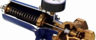
Checking the tightness of the heating system
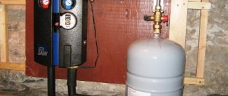
To ensure efficient and reliable operation of the heating system, they not only check the coolant pressure, but also test the equipment for leaks.
How this happens can be seen in the photo. As a result, you can monitor the presence of leaks and prevent equipment breakdown at the most crucial moment. The tightness test is carried out in two stages:
- cold water test. Pipelines and batteries in a multi-story building are filled with coolant without heating it, and pressure readings are measured. Moreover, its value during the first 30 minutes cannot be less than the standard 0.06 MPa. After 2 hours, losses cannot be more than 0.02 MPa. In the absence of gusts, the heating system of the high-rise building will continue to function without problems;
- test using hot coolant. The heating system is tested before the start of the heating period. Water is supplied under a certain compression, its value should be the highest for the equipment.
To achieve the optimal pressure value in the heating system, it is best to entrust the calculation of its arrangement to specialist heating engineers. Employees of such companies can not only carry out the appropriate tests, but also wash all its elements.
Testing is carried out before starting up the heating equipment, otherwise the cost of an error can be too expensive, and, as is known, it is quite difficult to eliminate an accident at sub-zero temperatures.
The pressure parameters in the heat supply scheme of a multi-storey building determine how comfortable you can live in each room. Unlike their own household with an autonomous heating system in a high-rise building, apartment owners do not have the opportunity to independently regulate the parameters of the heating structure, including temperature and coolant supply.
But residents of multi-storey buildings, if desired, can install such measuring instruments as pressure gauges in the basement and, in case of the slightest deviations in pressure from the norm, report this to the relevant utility services. If, after all the steps taken, consumers are still unhappy with the temperature in the apartment, perhaps they should consider organizing alternative heating.
As a rule, the pressure in the pipelines of domestic multi-story buildings does not exceed the maximum standards, but still, installing an individual pressure gauge will not be superfluous.
How to calculate ventilation pressure?
The total inlet pressure is measured at a cross-section of the ventilation duct located at a distance of two hydraulic duct diameters (2D). In front of the measurement point, there should ideally be a straight piece of air duct with a length of 4D and an undisturbed flow.
In practice, the conditions described above rarely occur, and then a honeycomb is installed in front of the desired location, which straightens the air flow.
Then a total pressure receiver is inserted into the ventilation system: at several points in the section in turn - at least 3. Based on the values obtained, the average result is calculated. For fans with a free input Pp, the input corresponds to the ambient pressure, and the excess pressure in this case is zero.
Diagram of the total pressure receiver: 1 - receiving tube, 2 - pressure converter, 3 - braking chamber, 4 - holder, 5 - annular channel, 6 - leading edge, 7 - inlet grid, 8 - normalizer, 9 - output signal recorder, α - angle at the peaks, h - depth of the valleys
If you measure a strong air flow, then you should determine the speed from the pressure, and then compare it with the cross-sectional size. The higher the speed per unit area and the larger the area itself, the more efficient the fan.
Total outlet pressure is a complex concept. The outgoing flow has a heterogeneous structure, which also depends on the operating mode and type of device. The air at the outlet has zones of return movement, which complicates the calculation of pressure and speed.
It will not be possible to establish a pattern for the time of occurrence of such a movement. The flow heterogeneity reaches 7-10 D, but this figure can be reduced by straightening grids.
The Prandtl tube is an improved version of the pitot tube: receivers are produced in 2 versions - for speeds less and more than 5 m/s
Sometimes there is a rotary elbow or a breakaway diffuser at the outlet of the ventilation device. In this case, the flow will be even more heterogeneous.
The pressure is then measured using the following method:
- Behind the fan, the first section is selected and scanned with a probe. The average total head and productivity are measured at several points. The latter is then compared with the input performance.
- Next, an additional section is selected - on the nearest straight section after exiting the ventilation device. From the beginning of such a fragment, measure 4-6 D, and if the length of the section is shorter, then select a section at the most distant point. Then take the probe and determine the productivity and average total head.
The calculated losses in the section after the fan are subtracted from the average total pressure at the additional section. The total outlet pressure is obtained.
Then the performance at the inlet, as well as at the first and additional sections at the outlet, is compared. The input indicator and one of the output indicators, which is closer in value, should be considered correct.
There may not be a straight line segment of the required length. Then select a section that divides the area to be measured into parts with a ratio of 3 to 1. The largest of these parts should be closest to the fan. Measurements cannot be made in diaphragms, dampers, bends and other connections with air disturbance.
Pressure drops can be recorded using pressure meters, draft meters in accordance with GOST 2405-88 and differential pressure gauges in accordance with GOST 18140-84 with an accuracy class of 0.5-1.0
In the case of roof fans, Pp is measured only at the inlet, and the static is determined at the outlet. The high-speed flow after the ventilation device is almost completely lost.
We also recommend reading our material on choosing pipes for ventilation.
Reasons for the drop in performance
Consumers often ask why pressure drops in closed and open heating systems. There are two reasons for these failures: coolant leakage and/or breakdown of elements in the heating device (boiler).
Coolant leak
In an open system, a test for tightness of connections will help increase the pressure. It is necessary to pay attention to all stains of dubious origin (they could remain from evaporated liquid), drops of water, puddles, and radiator joints (rusty marks are an indicator of leaks). If found, remove defects. But in a private home, the pipes are most often not made of steel, so it is almost impossible to see traces of leaks, especially if the water has had time to evaporate. This is a reason to seek help from specialists.
If a hidden pipeline is installed in the house, then the pressure drop in the boiler is also a reason to call a technician: he will drain the water, pump air into the system to detect leaks and eliminate the deficiency.
Features of pressure calculation
Measuring pressure in air becomes more difficult due to its rapidly changing parameters. You should buy electronic pressure gauges with a function for averaging the results obtained per unit of time. If the pressure jumps sharply (pulsates), dampers are useful to smooth out the differences.
The following principles should be remembered:
- total pressure is the sum of static and dynamic;
- the total pressure of the fan must be equal to the pressure loss in the ventilation network.
Measuring the static pressure at the outlet is not difficult. To do this, use a tube for static pressure: one end is inserted into the differential pressure gauge, and the other is directed into the section at the outlet of the fan. Based on the static pressure, the flow rate at the outlet of the ventilation device is calculated.
Dynamic pressure is also measured with a differential pressure gauge. Pitot-Prandtl tubes are connected to its connections. To one contact there is a tube for full pressure, and to the other - for static pressure. The result obtained will be equal to the dynamic pressure.
To find out the pressure loss in the air duct, you can monitor the flow dynamics: as soon as the air speed increases, the resistance of the ventilation network increases. Pressure is lost due to this resistance.
Anemometers and hot-wire anemometers measure flow velocity in an air duct at values up to 5 m/s or more; the anemometer should be selected according to GOST 6376-74
As the fan speed increases, the static pressure drops, and the dynamic pressure increases in proportion to the square of the increase in air flow. The total pressure will not change.
With a properly selected device, the dynamic pressure changes in direct proportion to the square of the flow rate, and the static pressure in inverse proportion. In this case, the amount of air used and the load of the electric motor, if they increase, will be insignificant.
Some requirements for the electric motor:
- low starting torque - due to the fact that power consumption changes in accordance with the change in the number of revolutions supplied to the cube;
- large stock;
- work at maximum power for greater savings.
The fan power depends on the total pressure, as well as on the efficiency and air flow. The last two indicators correlate with the throughput of the ventilation system.
At the design stage, you will have to set priorities. Take into account costs, loss of useful volume of premises, noise level.