Types of heat pump designs
The type of heat pump is usually denoted by a phrase indicating the source medium and coolant of the heating system.
The following varieties exist:
- TN “air-to-air”;
- HP "air - water";
- TN “soil - water”;
- TN "water - water".
The very first option is a conventional split system operating in heating mode. The evaporator is mounted outside, and a unit with a condenser is installed inside the house. The latter is blown by a fan, due to which warm air mass is supplied to the room.
If such a system is equipped with a special heat exchanger with pipes, the result is an air-water heat exchanger. It is connected to a water heating system.
A HP evaporator of the “air-to-air” or “air-to-water” type can be placed not on the street, but in the exhaust ventilation duct (it must be forced). In this case, the efficiency of the HP will be increased several times.
Heat pumps of the “water-to-water” and “ground-to-water” types use a so-called external heat exchanger or, as it is also called, a collector, to extract heat.
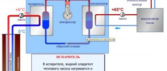
Schematic diagram of the operation of a heat pump
This is a long looped pipe, usually plastic, through which a liquid circulates, washing the evaporator. Both types of HP represent the same device: in one case, the collector is immersed in the bottom of a surface reservoir, and in the second - in the ground. The condenser of such a heat pump is located in a heat exchanger connected to the water heating system.
Connecting a VT according to the “water-water” scheme is much less labor-intensive than “ground-water”, since there is no need for excavation work. The pipe is laid in a spiral at the bottom of the reservoir. Of course, only a reservoir that does not freeze to the bottom in winter is suitable for this scheme.
Criterias of choice
At first glance, the need for labor-intensive laying of several hundred meters of plastic pipes on the bottom of a reservoir or even more costly drilling of wells for water-to-water HP seems doubtful. After all, there are air-to-air systems. There is no external collector at all. For example, a very high-quality Japanese air-to-water inverter HP produced by Mitsubishi Heavy.
It's simple - the density of water is 800 times greater than air. And warmth too. Therefore, the efficiency and economy of water systems will always be greater than that of Mitsubishi.
Power calculation
For preliminary calculations, a simplified formula is usually used: 700 watts of heat are required per 10 m2 of heated building. Then for a house with an area of 250 m2 you need to buy a water-to-water heat pump with a power of 175 kW.
To ensure hot water supply, the final figure must be increased by 15%.
This does not take into account the large difference between climatic zones, for example, Crimea and the Moscow region. The heat loss of the external enclosing structures of different buildings also differs greatly. There are other factors that must be taken into account in the calculation. Only specialists can do this.
The time has come to substantively study foreign experience
Almost everyone now knows about heat pumps capable of extracting heat from the environment to heat buildings, and if until recently a potential customer, as a rule, asked the perplexed question “how is this possible?”, Now the question “how is this correct” is increasingly heard do?".
It is not easy to answer this question.
In search of an answer to the numerous questions that inevitably arise when trying to design heating systems with heat pumps, it is advisable to turn to the experience of specialists from those countries where heat pumps on ground heat exchangers have been used for a long time.
A visit* to the American exhibition AHR EXPO 2008, which was undertaken mainly to obtain information about methods of engineering calculations of ground heat exchangers, did not bring direct results in this direction, but a book was sold at the ASHRAE exhibition stand, some of the provisions of which served as the basis for this publications.
It should be said right away that transferring American methods to domestic soil is not an easy task. For Americans, everything is not the same as in Europe. Only they measure time in the same units as we do. All other units of measurement are purely American, or rather British. Americans are especially unlucky with heat flow, which can be measured both in British thermal units per unit of time and in tons of cooling, which were probably invented in America.
The main problem, however, was not the technical inconvenience of recalculating the units of measurement adopted in the United States, to which one can get used to over time, but the absence in the mentioned book of a clear methodological basis for constructing a calculation algorithm. Too much space is devoted to routine and well-known calculation methods, while some important provisions remain completely undisclosed.
In particular, such physically related initial data for calculating vertical ground heat exchangers, such as the temperature of the liquid circulating in the heat exchanger and the conversion coefficient of the heat pump, cannot be set arbitrarily, and before proceeding with calculations related to unsteady heat exchange in the ground, it is necessary to determine the dependencies connecting these parameters.
The criterion for the efficiency of a heat pump is the conversion coefficient ?, the value of which is determined by the ratio of its thermal power to the power of the electric drive of the compressor. This value is a function of the boiling temperatures in the evaporator tu and the condensation temperatures tk, and in relation to water-to-water heat pumps, we can talk about the liquid temperatures at the outlet of the evaporator t2I and at the outlet of the condenser t2K:
? = ?(t2I,t2K). (1)
Analysis of the catalog characteristics of serial refrigeration machines and water-to-water heat pumps made it possible to display this function in the form of a diagram (Fig. 1).
Using the diagram, it is not difficult to determine the parameters of the heat pump at the very initial stages of design. It is obvious, for example, that if the heating system connected to the heat pump is designed to supply coolant with a supply temperature of 50°C, then the maximum possible conversion coefficient of the heat pump will be about 3.5. In this case, the glycol temperature at the outlet of the evaporator should not be lower than +3°C, which means that an expensive ground heat exchanger will be required.
At the same time, if the house is heated using underfloor heating, coolant with a temperature of 35°C will flow from the heat pump condenser into the heating system. In this case, the heat pump can operate more efficiently, for example with a conversion factor of 4.3, if the temperature of the glycol cooled in the evaporator is around -2°C.
Using Excel spreadsheets, you can express function (1) as an equation:
? = 0.1729 • (41.5 + t2I – 0.015t2I • t2K – 0.437 • t2K (2)
If, with the desired conversion coefficient and a given value of the coolant temperature in a heating system powered by a heat pump, it is necessary to determine the temperature of the liquid cooled in the evaporator, then equation (2) can be presented as:
(3)
You can select the coolant temperature in the heating system at given values of the heat pump conversion coefficient and the liquid temperature at the outlet of the evaporator using the formula:
(4)
In formulas (2)…(4) temperatures are expressed in degrees Celsius.
Having identified these dependencies, we can now move directly to the American experience.
Water-to-water heat pump diagram
In its operation, a heat pump uses the same principle as a refrigerator. Only in this case, special attention is paid not to the cooler (evaporator unit), but to the heat generator (condenser unit).
Well, the principle itself remains unchanged and assumes the following scheme of work:
Alternative energy sources
- The evaporator is introduced into an environment with a temperature above zero Celsius.
- The condenser is mounted indoors, connecting to it the direct pipe and the return pipe of the heating system.
- A cyclic pipeline is installed between the evaporator and the condenser, into which a compressor is inserted - a generator of pressure force and pressure.
- Refrigerant is poured into the cyclic pipeline - a substance that boils in the evaporator and turns into a liquid state in the condenser. Moreover, the cyclicity of evaporation and condensation is ensured by the compressor.
As a result, during the boiling process, the refrigerant takes heat from the water surrounding the evaporator and transports it to the condenser, where it transfers the accumulated energy to the heating system, turning from a gaseous state to a liquid one. After all, evaporation occurs with the extraction of energy, and condensation occurs with the release of calories.
Where is the evaporator installed?
Heat pump evaporator
To ensure efficient operation of the pump, we only need to bury the evaporator in the water, preferably below the freezing level of the liquid in the reservoir. After all, the water column maintains a temperature of 4-12 degrees Celsius almost all year round, providing heat pumps for hot water and heating systems with a constant flow of low-efficiency energy.
As a result, the platform for placing the evaporator can be any body of water with a depth of more than 1.5 meters and a constant liquid level. Well, if there is no such reservoir, then an ordinary well or borehole can be used as a source of low-efficiency heat. Moreover, the evaporator itself can be immersed not even in a well, but in a special tank filled with running water, which is pumped from a source and drained there.
Therefore, a water-to-water heat pump can be installed literally anywhere. After all, aquifers are hidden in almost any type of soil.
Calculation method for heat pumps
Of course, the process of selecting and calculating a heat pump is a very technically complex operation and depends on the individual characteristics of the object, but roughly it can be reduced to the following steps:
Heat loss through the building envelope (walls, ceilings, windows, doors) is determined. This can be done by applying the following relationship:
Qok = S*( tin – tout)* (1 + Σ β ) *n / Rt(W) where
tout – outside air temperature (°C);
tin – internal air temperature (°C);
S – total area of all enclosing structures (m2);
n – coefficient indicating the influence of the environment on the characteristics of the object. For rooms in direct contact with the outside environment through ceilings n=1; for objects with attic floors n=0.9; if the object is located above the basement n = 0.75;
β – coefficient of additional heat loss, which depends on the type of structure and its geographical location β can vary from 0.05 to 0.27;
Rt – thermal resistance, determined by the following expression:
Rt = 1/ αint + Σ ( δі / λі ) + 1/ αout (m2*°C / W), where:
δі / λі – calculated indicator of thermal conductivity of materials used in construction.
αout – coefficient of thermal dissipation of external surfaces of enclosing structures (W/m2*оС);
αinternal – thermal absorption coefficient of internal surfaces of enclosing structures (W/m2*оС);
— The total heat loss of the structure is calculated using the formula:
Qt.pot = Qok + Qi – Qbp, where:
Qi is the energy consumption for heating the air entering the room through natural leaks;
Qbp - heat generation due to the functioning of household appliances and human activities.
2. Based on the data obtained, the annual consumption of thermal energy is calculated for each individual object:
Qyear = 24*0.63*Qt. sweat.*(( d*( tin - tout.av.)/ ( tin - tout.))(kW/hour per year.) where:
tin – recommended indoor air temperature;
tout – outside air temperature;
tout.av – arithmetic mean value of the outside air temperature for the entire heating season;
d – number of days of the heating period.
3. For a complete analysis, you will need to calculate the level of thermal power required to heat the water:
Qgv = V * 17 (kW/hour per year) where:
V – volume of daily heating of water up to 50 °C.
Then the total consumption of thermal energy will be determined by the formula:
Q = Qgv + Qyear (kW/hour per year.)
Taking into account the data obtained, choosing the most suitable heat pump for heating and hot water supply will not be difficult. Moreover, the calculated power will be determined as: Qтн=1.1*Q, where:
Qтн=1.1*Q, where:
1.1 – correction factor indicating the possibility of increasing the load on the heat pump during the period of critical temperatures.
After calculating heat pumps, you can select the most suitable heat pump that can provide the required microclimate parameters in rooms with any technical characteristics. And given the possibility of integrating this system with a heated floor climate control system, one can note not only its functionality, but also its high aesthetic value.
Heat pumps: calculation, selection, installation
Operating principle of a heat pump
The use of alternative clean energy sources can prevent the looming energy crisis. Along with the search and development of traditional sources (gas, oil), a promising direction is the use of energy accumulated in reservoirs, soil, geothermal sources, technological emissions (air, water, wastewater, etc.). However, the temperature of these sources is quite low (0–25 °C) and for their effective use it is necessary to transfer this energy to a higher temperature level (50–90 °C).
This transformation is realized by heat pumps (TH), which are essentially vapor-compression refrigeration machines (Fig. 1). A low-temperature source (LTS) heats evaporator 3, in which the refrigerant boils at a temperature of –10…+5 °C. Next, the heat transferred to the refrigerant is transferred by the classical vapor-compression cycle to condenser 4, from where it is supplied to the consumer (HTP) at a higher level.
Heat pumps are used in various industries, residential and public sectors. Currently, more than 10 million heat pumps of various capacities are in operation in the world: from tens of kilowatts to megawatts. Every year the TN fleet is replenished by approximately one million units. Thus, in Stockholm, a heat pump station with a capacity of 320 MW, using sea water with a temperature of +4 °C in winter, provides heat to the entire city [4].
As recently as 2004, the installed heat pump capacity in Europe was 4,531 MW, and heat pumps worldwide have already generated thermal energy equivalent to 1.81 billion m3 of natural gas. Heat pumps using geothermal and groundwater are energy efficient. In the United States, federal legislation has approved requirements for the mandatory use of geothermal heat pumps (GHP) in the construction of new public buildings.
In Sweden, 50% of all heating is provided by ground source heat pumps. By 2021, the World Energy Committee predicts that the share of geothermal heat pumps will be 75%. The service life of the gas turbine unit is 25–50 years. The prospects for using heat pumps are shown in [5]. Heat pumps are divided according to the principle of operation (compressor, absorption) and the type of heat transfer chain “source-consumer”.
The following types of heat pumps are distinguished: “air-to-air”, “air-to-water”, “water-to-air”, “water-to-water”, “ground-to-air”, “ground-to-water”, where the heat source is indicated first. If only a heat pump is used for heating, the system is called monovalent. If, in addition to the heat pump, another heat source is connected, operating separately or in parallel with the heat pump, the system is called bivalent.
A heat pump with hydraulic piping (water pumps, heat exchangers, shut-off valves, etc.) is called a heat pump installation. If the medium cooled in the evaporator is the same as the medium heated in the condenser (“water-water”, “air-air”), then by changing the flows of these media it is possible to change the HP mode to the reverse (cooling to heating and vice versa) . If the media are gases, then such a change in regime is called a reversible pneumatic cycle, if liquids - a reversible hydraulic cycle (Fig. 2).
In the case where cycle reversibility is achieved by changing the direction of the refrigerant using a cycle reversibility valve, the term “heat pump operating in a reversible refrigeration cycle” is used.
Low-grade heat sources
1. Air
Air-to-water heat pumps are widely used in air conditioning systems. Outside air is blown through the evaporator, and the heat removed from the condenser heats the water used for indoor heating (Figure 3). The advantage of such systems is the availability of a low-grade heat source (air). However, the air temperature varies over a wide range, reaching negative values.
In this case, the efficiency of the heat pump is greatly reduced. Thus, a change in outside air temperature from +7 °C to –10 °C leads to a decrease in the performance of the heat pump by one and a half to two times. To supply water from heat pumps to heated rooms, heat exchangers are installed in them, called “fan coils” in the literature. Water is supplied to the fan coil units by a hydraulic system - a pumping station (Fig. 4). To increase the accuracy of maintaining room temperature and reduce inertia, storage tanks are installed in the hydraulic system. The capacity of the storage tank Vab [l] can be determined by the formula [8]:
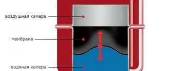
where Qx is the cooling capacity of the HP, kW; Vп — volume of refrigerated premises, m3; Vsyst — amount of water in the system, l; Z is the number of HP power stages. If Vab turns out to be negative, then the storage tank is not installed. To compensate for the thermal expansion of water in the hydraulic system, expansion tanks are installed on the suction side of the pump. The volume of the expansion tank Vрб [l] is determined by the formula [8]:
where Vsyst is the volume of the system, l; k is the coefficient of volumetric expansion of the liquid (water - 3.7 × 10⁻⁴, antifreeze - (4.0–5.5) × 10–4); Δt — liquid temperature difference (when operating only in cooling mode Δt = tamb – 4 °C, and when operating only in heat pump mode Δt = 60 – 4 = 56 °C); Psist - pressure in the system; Pprev—safety valve setting. The pressure in the Psist system depends on the relative position of the pumping station and the end user (fan coil).
If the pumping station is located below the consumer, then the pressure Psyst is determined as the maximum height difference (in bar) plus 0.3 bar. If the pumping station is located above all consumers, then Psyst = 1.5 bar. The expansion tank is pre-pumped with air to a pressure 0.1–0.3 bar less than the calculated one, and after installation the pressure is brought to normal. The design of expansion tanks is shown in Fig. 5.
Expansion units are produced to maintain pressure on the water side in large-volume heating and air conditioning systems. The unit is equipped with a freely programmable processor and can be connected via an interface to a central control panel. This simplifies control over the functioning of the system. Technical characteristics: volume 200–5000 l; maximum overpressure - 10 bar; maximum temperature - 120 °C.
The flow switch (RP) turns off the refrigeration machine in the absence of liquid flow, which prevents freezing of the liquid in the heat exchanger (HE). A three-way valve mixes two fluid streams ("A" and "B"), maintaining a given fluid temperature. The three-way valve is controlled by a microcontroller. The design of a three-way valve is shown in Fig. 6.
In the lower extreme position of the shut-off cone, the passage to flow “B” is closed; in the upper position of the cone, the passage to flow “A” is closed. To move the shut-off cone over the entire stroke from one extreme position to the other, a control supply voltage is supplied to the electric drive in the range from 0 to 10 V. The power supply to the electric motor is 24 V. A control signal about the position of the shut-off cone is issued from the drive output.
The full stroke time of the cone is 100–150 s. It is possible to manually move the cone using a hex key. Liquid leakage when the channel is closed does not exceed 1% of the throughput. If the three-way valve and hydraulic system malfunction, after the three-way valve, fluid will circulate through the check valve (OK). To set the calculated fluid flow in the system, a balancing valve is used, which is a high-precision manual or automatic control valve.
It has outputs for measuring fluid flow and pressure. Balancing valves are produced that are adjusted by the adjustment controller, for which the calculated values of flow and pressure are entered into the latter, after which the controller automatically sets the balancing valve to the required position. The expansion tank is connected to liquid feed valves (LPV) and air feed valves (APV). When installing the filter (F), pay attention to the direction of fluid flow through the filter.
An automatic air release valve (VV) is installed at the top point of the hydraulic circuit. The safety valve is adjusted to the maximum permissible pressure of the weakest element in the network plus 1 bar (7–10 bar). If necessary, work according to a bivalent circuit, you can connect an electrically heated boiler in parallel with the HP.
2. Water
Heat pumps with water heat sources (rivers, lakes, seas) use the accumulated energy of the Sun. This energy is an ideal source for heat pumps because... it is supplied continuously, although it is less accessible than air. The water temperature in non-freezing reservoirs does not fall below 4 °C, and artesian water has an almost constant temperature of 10–12 °C. Considering that when extracting heat, the water cannot be cooled below 0 °C, the temperature difference across the heat exchanger is several degrees.
At the same time, to increase the selection of the required amount of heat, it is necessary to increase the water consumption. For low-power HPs, it is not recommended to pump groundwater from a depth of more than 15 m. Otherwise, large costs will be required for pumps and their operation. The heat extraction circuit from the reservoir can be open or closed.
In the first case, water from the reservoir is pumped through a cooler, cooled and returned to the reservoir (Fig. 9). Such a system requires filtration of the water supplied to the cooler and periodic cleaning of the heat exchanger. As a rule, an intermediate collapsible heat exchanger is installed. Water intake and return must be carried out in the direction of groundwater flow to prevent “bypassing” of water.
The intake line must be equipped with a check valve 4, located at the intake point or after the deep pump 5. The supply and drainage of groundwater to the heat pump must be protected from freezing and laid with an inclination towards the well. The distance between intake 2 and return 1 wells must be at least 5 m. The water outlet point in the return well must be below the groundwater level. The volumetric flow rate of water is determined from the cooling capacity of the HP:
Qx = LρcpΔt, (3)
where L is the volumetric flow rate of water, m3/h; cp is the specific heat capacity of water, 1.163 × 10⁻³ kW⋅h/(kg⋅K); ρ—water density, 1000 kg/m3; Δt is the temperature difference between intake and return water. From here:
If we take Qx = 12 kW (determined from the heat pump’s passport), and Δt = 4 K, then L [m3/h] will be equal to:
The closed circuit is laid on the bottom of the reservoir. The approximate value of thermal power per 1 m of a closed circuit pipeline is about 30 W [2]. That is, to produce 10 kW of heat, the circuit must have a length of 300 m. To prevent the circuit from floating, a load weighing about 5 kg must be installed per linear meter.
3. Soil
Ground HP uses thermal energy accumulated in the soil due to its heating by the Sun or other sources. The heat accumulated in the soil is transformed using horizontally laid ground heat exchangers (also called ground collectors) or using vertically located heat exchangers (ground probes). As a rule, ground heat exchangers are usually made of polyethylene or metal-plastic pipes with a diameter of 25–40 mm.
In a horizontal design, the pipeline in which the liquid circulates is buried in the ground to a depth below the soil freezing level (1.2–1.5 m). The minimum distance between pipes is 0.7–1 m. Depending on the diameter of the pipe, 1.4–2 m of pipe can be laid for each square meter of heat intake area. The length of each horizontal collector branch should not exceed 100 m, otherwise the pressure loss in the pipe and the required pump power are too high.
The amount of transformed heat, and, consequently, the size of the required surface for the location of a soil collector, significantly depends on the thermophysical properties of the soil and the climatic conditions of the area. Thermophysical properties, such as heat capacity and thermal conductivity, very much depend on the composition and condition of the soil. In this regard, the determining factors are the proportion of water, the content of mineral components (quartz, feldspar), the proportion and size of pores filled with air.
The higher the proportion of water and mineral components and the lower the pore content, the higher the storage properties and thermal conductivity of soil. The average value of the specific thermal power of the soil is given in table. 1 [7]. The required area S [m2] for the location of the collector is calculated:
S = Qx/g, where (5)
Qх = Qт – Pн, (6)
where Qt is the heat output of the heat pump, W; Pn — power consumption of the transformer from the network, W; g is the specific power of the soil collector, W/m2. So, if the cooling capacity of the HP is 10 kW, then in sandy wet soil (20 W/m2) an area S [m2] will be required to place the collector:
To transform heat from such an area, it is necessary to lay polyethylene pipes with a diameter of 25 × 2.3 mm and a length of 500 × 1.4 = 700 m in the ground (1.4 is the specific pipe consumption per square meter of area). Pipes must be laid in separate circuits of 100 m each, i.e. seven circuits. All distributors and manifolds should be located in accessible locations for inspection, for example, in separate distribution shafts outside the house or in the basement shaft of the house.
Fittings must be made of corrosion-resistant materials. All pipelines in the house and entries through the wall must be carefully thermally insulated, ensuring diffusion impermeability to steam, in order to avoid the appearance of condensation, since the supply and return lines contain cold (relative to the basement temperature) coolant. With the vertical design of the soil probe, a well 60–200 m deep is drilled, into which several U-shaped pipelines are lowered (Fig. 11). In clayey, moist soil with a heat pump cooling capacity of 10 kW, the probe length L [m] (well depth) should be:
It is advisable to make two loops with a depth of 50 m and a diameter of Dу = 32 × 3 mm. The total length of the pipes will be 200 m. The well with the pipes is filled with bentonite, which conducts heat well. The amount of coolant is determined by the internal volume of the collector (probe) pipes and supply pipes. The diameter of the supply pipes is taken to be larger than the collector pipe. In our example, with a probe pipe Dу = 32 × 3 mm and a supply pipe Dу = 40 × 2.3 mm, 10 m long, the internal volume (Table 2), taking into account the supply line, will be:
2 × 100 × 0.531 + 10 × 0.984 = 116.04 l.
The heat pump coolant flow rate is determined from the heat pump data sheet. Let’s take 1600 l/h, then the flow rate per loop will be 800 l/h. Pressure loss in pipes depends on the diameter of the pipes, density and flow rate of the coolant and is determined according to the data of the pipe manufacturer. Thus, for HDPE pipes (high density polyethylene) 32 × 3 mm and a flow rate of 800 l/h, the loss value is 154.78 Pa/m, and for pipes with a diameter of 40 × 2.3 - 520.61 Pa/m [7].
Hence the total pressure drop in the network will be 36161.1 Pa, which must be taken into account when choosing a pump. The service life of a ground collector depends on the acidity of the soil: with normal acidity (pH = 5) this value is 50–75 years, with increased acidity (pH > 5) - 25–30 years.
Heat pump efficiency
As the main indicator of the efficiency of a heat pump, the conversion coefficient or heating coefficient COP (Coefficient of Performance) is used, equal to the ratio of the thermal output of the heat pump to the power consumed by the compressor. In cooling mode, the EER (Energy Efficiency Ratio) is used to evaluate efficiency, equal to the ratio of the cooling capacity of the heat pump to the power consumed by the compressor:
where Qr is the energy given off by the HTP; Qc is the thermal energy taken from the INT; N – consumed electricity; tк and t0 are the condensation and boiling temperatures in the heat pump. Temperature tk is determined by the condensation pressure of the refrigerant in the HP, and t0 is determined by the temperature of the HP. So, if we take t0 = 281.16 K (8 °C) and tк = 323.16 K (50 °C), then COP will be equal to 7.7. If heat is removed by water, then various refrigerants can achieve the following temperatures [1]: with R717, R502, R22 about +50 °C, with R134a +70 °C, and with R142 +100 °C.
You should remember the basic rule that follows from formula (4): the smaller the temperature difference between the heat source and the heat receiver in the heat pump, the higher the conversion coefficient. When heat pumps simultaneously use heat and cold (for example, cooling refrigerators and heating office premises), then:
With an equipotential cycle, Qr = Qc takes place:
At the above temperatures, the total conversion coefficient can reach 12.7, which characterizes the high energy efficiency of the heat pump. Real SOPs are somewhat lower and are on the order of three to five. In absorption heat pumps, the conversion coefficient is lower than in compression heat pumps due to large losses in the elements of the absorption circuit.
Thus, when using groundwater with t0 = 281.16 K (8 °C) and useful heat temperature tk = 323.16 K (50 °C), the absorption heat conversion coefficient will be only 1.45 [1]. The useful heat temperature in absorption heat pumps also depends on the heating temperature of the generator. At the temperatures indicated above, the heating of the generator must be at least 150 °C. During the heating season (October-May), heating 100 m2 of living space with an electric boiler will require 37.440 kW of electricity, and with a heat pump - 12.024 kW. At a tariff of 0.24 UAH per 1 kWh of electricity, the savings will be 6,100 UAH. For Russian reality: tariff - 3 rubles, savings - 76 rubles / hour.
According to www.aeroprof.by, the use of HP is 1.2–1.5 times more profitable than the most efficient gas boiler house. The cost of a heat pump can be approximately estimated at 850–2500 UAH (in terms of rubles, this is approximately 5–8 thousand rubles) per 1 kW of generated thermal power. Payback period is 7–14 years.
Selection of equipment for HP
The choice of equipment begins with calculating the heat consumption of the building. Currently, there are a variety of programs for calculating heat consumption on a PC, which can be found on the Internet or obtained from equipment suppliers. An approximate calculation can be made based on the heated area of the building and the amount of hot water consumed.
Also, in case of periodic power outages, it is necessary to increase the thermal power of the heat pump. If the power outage does not exceed two hours, this factor can be ignored. The specific heat consumption depends on the type of building: low consumption building, i.e. modern materials, wall insulation, double-glazed windows (40 W/m2); new building with good thermal insulation (50 W/m2); building with standard thermal insulation (80 W/m2); old buildings without special insulation (120 W/m2). Accounting for additional thermal power to compensate for heat losses during planned power outages is carried out as follows. First, the daily (24 hour) heat consumption Qday [kW] is determined:
where Qtn is the heat output of the heat pump, kW; τtk — time without electricity, hours. Calculation of additional thermal power for preparing hot water is made based on the consumption of about 50 l/day by one person. water with a temperature of 45 °C, which corresponds to 0.25 kW/person. A more accurate calculation can be performed using the data in table. 3.
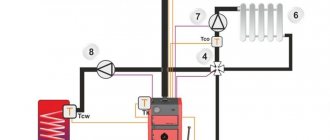
Let's consider an example of building a heat pump with a reversible hydraulic cycle, operating year-round in two modes (cooling or heating) depending on the period of the year, using equipment and software from CIAT (France). Initial requirements: heating capacity 510 kW; a low-temperature source is sea water with a temperature in the warm period of the year ≤ 20 °C, in the cold period of the year - 7 °C; high-temperature consumer: water with a temperature at the heat exchanger outlet of +55 °C; minimum outdoor temperature –10 °C (Crimea, Ukraine).
We will solve this problem using a heat pump with a reversible hydraulic cycle, the diagram of which is shown in Fig. 2. Considering that the outside air temperature is negative (–10 °C), we use a dual-circuit system in the heat pump. The primary circuit uses an ethylene glycol solution with a freezing point below -10 °C (20% mixture of ethylene glycol and water).
In accordance with the initial requirements, we select the temperature difference in the high-temperature circuit Δtout = 5 °C (50/55 °C). Then the coolant temperatures in the condenser circuit should be 55/60 °C respectively. To obtain such temperatures in a heat pump, it is advisable to use R134a refrigerant [1]. In accordance with the initial requirements, we set the temperature difference INT to be 7/4 °C, then in the evaporator circuit the temperature difference, accordingly, will be 5/2 °C.
Using the CIAT equipment selection program, we will determine the type and parameters of the heat pump in heating and cooling operating modes. The program selected the Hydrociat 2500BX LW/LWP R134a heat pump with the parameters given in table. 4. Next, we select a high-temperature plate heat exchanger “heat pump-consumer” according to the following initial data (heating mode): water temperature (outlet/input) 55/50 °C; temperature of 20% ethylene glycol solution in the primary circuit (outlet/inlet) 60/55 °C; consumption of 20% ethylene glycol solution: 93.4 m3/h (Table 1).
The CIAT program selects a plate heat exchanger PWB 30-11 with a capacity of 517 kW (Table 5). We select a low-temperature heat exchanger “sea water–heat pump” in heating mode according to the following initial data: source of low-grade heat (primary circuit) - sea water with a temperature (input/outlet) of 7/4 °C; temperature of 20% ethylene glycol solution in the primary circuit 5/2 °C; consumption of 20% ethylene glycol solution is 102.8 m3/h.
The CIAT program selects the plate heat exchanger PWB 45 11. Let's perform a test calculation of the previously calculated heat exchanger PWB 30-11 with 43 plates for the warm period of the year and determine the water temperature at the outlet/inlet to the consumer. The CIAT program showed that in summer the performance of the PWB 30-11 heat exchanger will be 437 kW and the coolant temperatures will be (outlet/inlet) 7.5/12 °C (Table 7). So, the selected Hydrociat 2500BX LW/LWP heat pump provides: in the cold season, a heating output of 517 kW with a power consumption of 191 kW; in the warm season, the cooling capacity is 395.9 kW with a power consumption of 158 kW.
conclusions
- Heat pumps using renewable heat sources are the most energy efficient heating equipment.
- Systems built on the basis of TN are reliable, safe and durable.
- Producing heat through a heat pump is an environmentally friendly technological process.
- Modern climate control equipment (for example, the French CIAT) makes it possible to create HP with a performance of tens of kilowatts to a megawatt and even more.
Types of Heat Pumps
Heat pumps are divided into three main types based on the source of low-grade energy:
- Air.
- Priming.
- Water - the source can be groundwater and surface water bodies.
For water heating systems, which are more common, the following types of heat pumps are used:
Air-to-water is an air-to-air heat pump that heats a building by drawing in air from outside through an external unit. It works on the principle of an air conditioner, only in reverse, converting air energy into heat. Such a heat pump does not require large installation costs; there is no need to allocate a plot of land for it and, especially, to drill a well. However, operating efficiency at low temperatures (-25ºС) is reduced and an additional source of thermal energy is required.
The “ground-water” device is a geothermal device and extracts heat from the ground using a collector placed at a depth below freezing of the soil. There is also a dependence on the area of the site and the landscape if the collector is located horizontally. For a vertical location, you will need to drill a well.
“Water-water” is installed where there is a pond or groundwater nearby. In the first case, the collector is laid on the bottom of the reservoir, in the second, a well or several are drilled, if the area of the site allows. Sometimes the depth of groundwater is too great, so the cost of installing such a heat pump can be very high.
Each type of heat pump has its own advantages and disadvantages; if the building is located far from a body of water or the groundwater is too deep, then “water-to-water” will not work. “Air-water” will be relevant only in relatively warm regions, where the air temperature in the cold season does not fall below -25º C.
Stages of calculating a heat pump
The first stage is the calculation of heat loss
The main thing that needs to be done first is to determine the heat loss of the building. To calculate heat loss, it is better to contact specialists. Now there are enough programs that can calculate heat output with high accuracy both for the entire house and for each room separately. There are also simple programs on the Internet that you can use yourself. You can calculate it manually by calculating heat loss through walls, floors, roof, windows and ventilation. To make such a calculation, you must have certain knowledge. The easiest way is to use averaged data. To pre-calculate a heat pump, it will be enough to use any method. Considering that the cost per kilowatt of a heat pump is high and if the final decision is made to install a geothermal system, the calculation must be quite accurate and performed by specialists. A miss by one kilowatt can cost an additional 30-50 thousand rubles.
Second phase. Calculation of the external circuit of the heat pump
The source of low-grade heat can be air, soil, water, wastewater. At this stage, the length of the pipes and the required area of the site for the horizontal geothermal circuit are calculated. For vertical probes, the length of the wells with geothermal probes placed in them is determined. For an open well-to-well scheme, the required flow rate is calculated and a submersible pump is selected.
Particular attention must be paid to the calculation of the air-to-water heat pump. The fact is that the heat source, air, unlike geothermal systems, greatly influences the thermal output of the heat pump. All manufacturers, in the specifications, write the output power for external temperatures from +2C to +7C. Some point to +2C, others to +5C, others to +7C. You need to pay attention to these parameters. What's happening? As the temperature drops, the power output of the air-to-water heat pump drops. Let’s say at +5C the power was 10 kW, then at -10C the power can decrease to 6-7 kW. Compressor manufacturers have special tables or graphs. These tables indicate the compressor power depending on the temperature of the incoming low-grade heat. Using the tables, you can select a heat pump for a certain negative temperature. Let’s say we picked up a power of 16 kW at +5C, at -10C it will produce the required 10 kW.
Method for calculating heat pump power
In addition to determining the optimal energy source, you will need to calculate the heat pump power required for heating. It depends on the amount of heat loss from the building. Let's calculate the power of a heat pump for heating a house using a specific example.
To do this, we use the formula Q=k*V*∆T, where
- Q is heat loss (kcal/hour). 1 kW/h = 860 kcal/h;
- V is the volume of the house in m3 (the area is multiplied by the height of the ceilings);
- ∆T – the ratio of the minimum temperatures outside and inside the room during the coldest period of the year, °C. From the internal tº we subtract the external one;
- k is the generalized heat transfer coefficient of the building. For a brick building with masonry in two layers k=1; for a well-insulated building k=0.6.
Thus, the calculation of the heat pump power for heating a brick house of 100 sq.m and a ceiling height of 2.5 m, with a ttº difference from -30º outside to +20º inside, will be as follows:
Q = (100x2.5) x (20- (-30)) x 1 = 12500 kcal/hour
12500/860= 14.53 kW. That is, for a standard brick house with an area of 100 m, you will need a 14-kilowatt device.
The consumer makes the choice of the type and power of the heat pump based on a number of conditions:
- geographical features of the area (proximity of reservoirs, presence of groundwater, free land for a collector);
- climate features (temperature);
- type and internal volume of the room;
- financial opportunities.
Taking into account all the above aspects, you can make the optimal choice of equipment. For a more efficient and correct selection of a heat pump, it is better to contact specialists; they will be able to make more detailed calculations and provide the economic feasibility of installing the equipment.
Heat pumps have been used for a long time and very successfully in domestic and industrial refrigerators and air conditioners.
Today, these devices have begun to be used to perform the opposite function - heating a home during cold weather.
Let's look at how heat pumps are used to heat private homes and what you need to know in order to correctly calculate all its components.
Heat pump intermediate heat exchanger
When implementing a project to install a heat pump using an open circuit, it is recommended to install an intermediate heat exchanger. It is needed to protect the freon part and, most importantly, the heat pump compressor from water ingress. When the heat exchanger defrosts, water can enter the system with freon, the compressor will pump this water and a water hammer will occur, which will damage the compressor. The water will mix with the oil and getting it out will be very problematic. Such a heat exchanger is installed between the well and the heat pump. The heat pump section and the intermediate heat exchanger are filled with brine with a freezing point of -10 -15C. Accordingly, if the protection does not work and the water freezes in the heat exchanger, the brine will not freeze and will not defrost the heat pump heat exchanger. The cost of an intermediate heat exchanger depends on its design and size. And the latter depends on the power of the heat pump.
It is best to use a collapsible version as an intermediate heat exchanger. But its cost is 2-4 times higher than that of a soldered one.
If the well is clean and the well flow rate is good, then you can do without an intermediate heat exchanger, but it is better with one.
Example of heat pump calculation
We will select a heating element for the heating system of a one-story house with a total area of 70 square meters. m with a standard ceiling height (2.5 m), rational architecture and thermal insulation of enclosing structures that meet the requirements of modern building codes. For heating the 1st sq. m of such an object, according to generally accepted standards, it is necessary to spend 100 W of heat. Thus, to heat the entire house you will need:
Q = 70 x 100 = 7000 W = 7 kW of thermal energy.
We choose a heat pump of the TeploDarom brand (model L-024-WLC) with a thermal power W = 7.7 kW. The compressor of the unit consumes N = 2.5 kW of electricity.
Reservoir calculation
The soil in the area allocated for the construction of the collector is clayey, the groundwater level is high (we assume the calorific value p = 35 W/m).
The collector power is determined by the formula:
Qk = W – N = 7.7 – 2.5 = 5.2 kW.
L = 5200 / 35 = 148.5 m (approx.).
Based on the fact that laying a circuit longer than 100 m is irrational due to excessively high hydraulic resistance, we accept the following: the heat pump collector will consist of two circuits - 100 m and 50 m long.
The area of the site that will need to be allocated for the collector will be determined using the formula:
S = L x A,
Where A is the step between adjacent sections of the contour. We accept: A = 0.8 m.
Then S = 150 x 0.8 = 120 sq. m.
Operating principle of a heat pump
The coolant is heated from a source of low-potential (5...10 °C) heat. The pump compresses the refrigerant, the temperature of which rises (50...60 °C) and heats the coolant of the heating system or hot water supply.
During the operation of the HP, three thermal circuits are involved:
- external (system with coolant and circulation pump);
- intermediate (heat exchanger, compressor, condenser, evaporator, throttle valve);
- consumer circuit (circulation pump, heated floor, radiators; for hot water supply - tank, water points).
The process itself looks like this:
Thermal energy removal circuit
- The soil heats the saline solution.
- The circulation pump lifts the brine into the heat exchanger.
- The solution is cooled by a refrigerant (freon) and returned to the ground.
- Liquid freon, evaporating, takes away thermal energy from the brine.
- The compressor compresses the refrigerant, causing its temperature to rise sharply.
- In the condenser, freon transfers energy through the evaporator to the coolant of the heating circuit and becomes liquid again.
- The cooled refrigerant goes through the throttle valve to the first heat exchanger.
- The heated coolant of the heating system is drawn by the circulation pump to the dissipating elements.
- Transfers thermal energy to the air mass of the room.
- The cooled coolant returns through the return pipe to the intermediate heat exchanger.
Video with a detailed description of the process:
Payback of a heat pump
When it comes to how long it will take for a person to get back his money invested in something, we mean how profitable the investment itself was. In the heating sector, everything is quite difficult, since we provide ourselves with comfort and warmth, and all systems are expensive, but in this case, you can look for an option that would return the money spent by reducing costs during use. And when you start looking for a suitable solution, you compare everything: a gas boiler, a heat pump or an electric boiler. We will analyze which system will pay off faster and more efficiently.
The concept of payback, in this case, the introduction of a heat pump to modernize the existing heat supply system, simply put, can be explained as follows:
There is one system - an individual gas boiler, which provides autonomous heating and hot water. There is a split-system air conditioner that provides cold air to one room. 3 split systems installed in different rooms.
And there is a more economical advanced technology - a heat pump, which will heat / cool houses and heat water in the right quantities for a house or apartment. It is necessary to determine how much the total cost of equipment and initial costs has changed, and also to estimate how much the annual costs of operating the selected types of equipment have decreased. And determine how many years it will take for more expensive equipment to pay for itself with the resulting savings. Ideally, several proposed design solutions are compared and the most cost-effective is selected.
We will carry out calculations and find out what is the payback period for a heat pump in Ukraine
Let's look at a specific example
- The house has 2 floors, is well insulated, with a total area of 150 sq. m.
- Heat distribution/heating system: circuit 1 – heated floor, circuit 2 – radiators (or fan coils).
- A gas boiler for heating and hot water supply (DHW) has been installed, for example 24 kW, double-circuit.
- Split air conditioning system for 3 rooms of the house.
Annual heating and water heating costs
| Max. heat output of HP for heating, kW | 19993,59 |
| Max. power consumption of the heat pump when operating for heating, kW | 7283,18 |
| Max. heating capacity of the heating element for domestic hot water supply, kW | 2133,46 |
| Max. HP power consumption when operating on DHW, kW | 866,12 |
- The approximate cost of a boiler room with a 24 kW gas boiler (boiler, piping, wiring, tank, meter, installation) is about 1000 Euros. An air conditioning system (one split system) for such a house will cost about 800 euros. In total, including the installation of the boiler room, design work, connection to the gas pipeline network and installation work - 6,100 euros.
- The approximate cost of a Mycond heat pump with an additional fan coil system, installation work and connection to the electrical network is 6,650 euros.
- The growth of capital investments is: K2-K1 = 6650 – 6100 = 550 euros (or about 16500 UAH)
- The reduction in operating costs is: C1-C2 = 27252 – 7644 = 19608 UAH.
- Payback period Tokup. = 16500 / 19608 = 0.84 years!
Ease of use of the heat pump
Heat pumps are the most versatile, multifunctional and energy-efficient equipment for heating a home, apartment, office or commercial facility.
An intelligent control system with weekly or daily programming, automatic switching of seasonal settings, maintaining the temperature in the house, economical modes, control of a slave boiler, boiler, circulation pumps, temperature control in two heating circuits, is the most advanced and advanced. Inverter control of the compressor, fan, and pumps allows for maximum energy savings.
Preliminary calculation of a heat pump
Before manufacturing a water-to-water pump, the project is calculated and the required power of the equipment is determined. After all, such a project will differ in execution in each specific case. The calculation must take into account the heat loss of the building, the hot water supply circuit, the additional consumption of thermal energy, etc. All this can only be done individually in each specific case.
Well for a heat pump
You can do an approximate calculation of a water-to-water heat pump yourself.
How to do it? First you need to calculate the area of the room that you are going to heat. The relationship between area and the required amount of heat is described by the ratio: per 10 square meters, 0.7 kilowatts of thermal energy is required. It is easy to calculate that a house with an area of 100 square meters will require an installation with a capacity of 7 kilowatts. If, in addition to heating, your pump will also provide hot water supply, then you need to add a reserve of about 20 percent to the resulting figure. The above calculation formula is valid for houses with an average degree of thermal insulation. The ceiling height in the rooms is up to 2.7 meters. A more accurate and final calculation of the water-to-water pump is performed by specialists who will manufacture and install the equipment. In it they take into account all the additional nuances.
Heat pump operation when working according to the ground-water scheme
The collector can be installed in the ground in three ways.
Horizontal option
The pipes are laid in trenches in a “snake” pattern to a depth exceeding the freezing depth of the soil (on average, from 1 to 1.5 m).
Such a collector will require a fairly large plot of land, but any homeowner can build it - no skills other than the ability to work with a shovel will be required.
It should, however, be taken into account that constructing a heat exchanger manually is a rather labor-intensive process.
Vertical option
Collector pipes in the form of loops shaped like the letter “U” are immersed in wells with a depth of 20 to 100 m. If necessary, several such wells can be built. After installing the pipes, the wells are filled with cement mortar.
The advantage of a vertical collector is that its construction requires a very small area. However, there is no way to drill wells more than 20 m deep on your own - you will have to hire a team of drillers.
Combined option
This collector can be considered a type of horizontal, but its construction will require much less space.
A round well with a depth of 2 m is dug on the site.
The heat exchanger pipes are laid in a spiral, so that the circuit looks like a vertically installed spring.
Upon completion of installation work, the well is backfilled. As in the case of a horizontal heat exchanger, all the necessary work can be done with your own hands.
The collector is filled with antifreeze - antifreeze or ethylene glycol solution. To ensure its circulation, a special pump is inserted into the circuit. Having absorbed the heat of the soil, the antifreeze enters the evaporator, where heat exchange occurs between it and the refrigerant.
It should be taken into account that unlimited heat extraction from the ground, especially when the collector is located vertically, can lead to undesirable consequences for the geology and ecology of the site. Therefore, in the summer, it is highly desirable to operate HPs of the “soil-water” type in reverse mode - air conditioning.
A gas heating system has a lot of advantages and one of the main ones is the low cost of gas. The heating diagram for a private house with a gas boiler will tell you how to arrange heating of your home with gas. Let's consider the heating system design and replacement requirements.
Read about the features of choosing solar panels for heating your home in this topic.
How does a ground source heat pump work? Principle of operation.
To obtain heat from the ground, a ground heat exchanger is needed. To do this, simply place a pipe in the ground, forming a loop in which a liquid circulates - popularly called brine. The loop (in practice there are several) passes through the heat pump's evaporator, where the brine temperature decreases and becomes lower than the ground temperature. As the brine passes further through the pipe in the ground, it gradually heats up. At the end it goes back to the evaporator, where it gives off heat.
Thus, the brine mediates the exchange of temperature differences between the soil and the pump evaporator.
The heat exchanger can be horizontal or vertical. The size of the land plot helps in choosing a solution - several hundred square meters are required for the manufacture of a horizontal heat exchanger, and several dozen are enough for vertical probes.
It is important that the volume of the heat exchanger is large - for the entire heating season, the pump receives several megawatt-hours of heat from the ground. If it is too small, it is subject to excessive cooling and, as a result, the pump cannot operate correctly. The control system of a ground source heat pump usually switches it off when the brine temperature drops to -7°C, because below this value the circuit is excessively disrupted.
Ground source heat pump with horizontal heat exchanger.
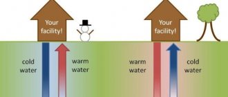
In the case of a heat exchanger made of pipes located horizontally, the optimal depth is 0.2 - 0.5 m below the freezing line. However, if there is a watercourse at a relatively shallow depth, then the best solution is to place the pipes in it. The heat pump then achieves a higher performance coefficient Kp .
The pipes of the horizontal heat exchanger are laid in a pre-prepared pit with dimensions corresponding to the required surface of the heat exchanger. They are led in the form of a coil (in bends) over the entire surface of the pit, maintaining certain intervals between adjacent sections. Intervals should not be less than 0.4 m and no more than 1.2 m, taking into account the type of soil from which its ability to “regenerate” (adding heat) derives. The longer the ground surface is frozen, the longer the interval should be.
It must be remembered that the thermal power of the heat exchanger does not flow from the length of the pipe, only from the surface of the soil on which it is laid. Small gaps do not allow receiving more heat from it, due to the need to use a long pipe. This translates into higher investment costs as well as operating costs, because in order to pump brine through a long pipe, a circulation pump with more power is needed. Because of this too large gap between the pipes, the heat does not flow in the designed amount, so the heat exchanger output is less.
Ground heat exchanger project.
Designing the appropriately sized ground heat exchanger is key to proper heat pump operation. To calculate its required value, information about the required power of the heat pump is required. If it is not in the technical characteristics of the device, then it is enough to know that it corresponds to the thermal power reduced by the compressor power. If we do not know what power the compressor has, but we have information about the performance coefficient Kp , then we can calculate the cooling power with sufficient accuracy using the formula:
Qcool = (Kp – 1)/Kp • Qheat.
It is necessary to pay attention that the substituted values are achieved at a temperature corresponding to that prevailing both in the soil and in the heating system when the pump is operating at full power (for example, 0/35 - brine temperature 0 degrees Celsius, heating system 35 degrees Celsius).
Calculation of the heat exchanger surface of a horizontal ground source heat pump.
The force with which a ground heat exchanger transfers heat depends on the type of soil, namely its moisture content. Depending on this, to calculate the surface of a horizontal heat exchanger, the following values of the thermal power of the soil qg (for polyethylene pipes) are taken:
- sandy dry – 10 W/m2
- sandy, wet – 15-20 W/m2
- clayey dry – 20-25 W/m2
- clayey, wet – 25-30 W/m2
- wet (water-bearing) – 35-40 W/m2.
Of course, these are indicative values.
It is difficult to assess whether the soil is the same throughout the area intended for the heat exchanger until construction begins, so it is better to take a lower value for calculation. In a properly designed system, the heat pump compressor runs from 1800 to 2400 hours per year, the ground heat output results in longer operating hours.
The surface of the heat exchanger is calculated using the formula:
A = Q/qg
Example: the energy requirement of a house for heating is 14 kW, and the pump will satisfy them in full (must operate in a monovalent system). The selected device receives a thermal power (heating) of 14 kW for parameters 0/35, while achieving an efficiency coefficient Kp = 4.5. The cooling power is therefore Qcool = (4.5-1)/4.5 • 14 = 10.9 kW, that is, 10900 W. The heat exchanger must be made in dry clay soil, so its area must be A = 10 900/20 = 545 m2. Attention is drawn to the fact that in the case of aquiferous soil, the heat exchanger can be half as large, but if the soil is sandy, then its area will occupy more than 1000 m2. In such a situation, the best solution is to place the pipes vertically.
Heat exchanger of a vertical ground source heat pump.
The heat pump achieves a higher performance coefficient Kp when the heat exchanger tubes are located vertically in the ground - at a depth of 40-150 m. This is due to the fact that at a depth below 10 m the ground temperature is approximately 10 degrees Celsius all year round - that is, in winter almost ten more than at a depth of 1.5 meters.
Making a vertical heat exchanger, however, is clearly more expensive than a horizontal one. These are vertical sections of pipe that form a loop (the pipe passes down through the holes, at the bottom it turns around and goes up). They are called geothermal probes. In this case, they are calculated not by area, but by the total length of the heat exchanger, which usually consists of more than one probe.
In vertical wells, one or two pairs of pipes (U or Y type probes) are placed. The insertion of the well pipe is facilitated by a head - an element connecting the vertical pipes, which can be adapted to use an additional filling pipe. The head is pushed into the holes, and with it the heat exchanger pipes. Then liquid concrete is poured into the well.
In a Y-type heat exchanger, liquid flows down to the head in one pipe and returns from it in the other. In a double U type heat exchanger, it flows with two pipes down and two up.
The distance between drilling points up to 50 m deep should not be less than 5 m, and in the case of deeper ones, from 8 to 15 meters. Must be located on a line perpendicular to the direction of water flow.
Calculation of the length of the heat exchanger of a vertical ground source heat pump.
In this case, it is important how the properties of the soil change with depth. Geological maps and documentation of wells previously drilled nearby can provide information. On this basis, it is possible to estimate the thickness of individual soil layers and calculate the average thermal conductivity coefficient for the area in which the heat exchanger tubes should be placed.
Calculations, however, are not able to take into account all movements of groundwater and in practice it often happens that the obtained result differs significantly from reality. To be sure that the vertical heat exchanger will work properly, it is necessary to carry out a soil survey in the area where drilling is to be done. In this case, the soil heat productivity qg also depends on its type.
For PE80 pipes it is:
- dry sandy soil – 10-12 W/m;
- sandy wet – 12-16 W/m;
- medium clay dry – 16-18 W/m;
- medium clay wet – 19-21 W/m;
- heavy clay dry – 18-19 W/m;
- heavy clayey wet – 20-22 W/m;
- wet (water-bearing) – 25-30 W/m.
It is necessary to take into account the thickness of individual layers of a certain type of soil and on this basis calculate the overall performance of each probe.
The heat production of soil, in which both layers are dry, like aquifers, when using double U type probes (four pipes in a well), averages about 50 W/m. Tentatively, it can be assumed that in the case of the applicants’ heat pump in the example of calculating a horizontal heat exchanger (with a cooling capacity of 10.9 kW), holes with a total length of L = 10,900/50 = 218 m are required, that is, for example, four 55 meters each.
Calculation of a horizontal heat pump collector
The efficiency of a horizontal collector depends on the temperature of the medium in which it is immersed, its thermal conductivity, and the area of contact with the surface of the pipe. The calculation method is quite complex, so in most cases averaged data is used.
It is believed that each meter of heat exchanger provides the HP with the following thermal power:
- 10 W – when buried in dry sandy or rocky soil;
- 20 W – in dry clay soil;
- 25 W – in wet clay soil;
- 35 W – in very damp clay soil.
Thus, to calculate the length of the collector (L), the required thermal power (Q) should be divided by the calorific value of the soil (p):
L = Q/p.
The values given can only be considered valid if the following conditions are met:
- The area of land above the sewer is not developed, shaded or planted with trees or bushes.
- The distance between adjacent turns of the spiral or sections of the “snake” is at least 0.7 m.
What is cheaper for heating: electricity, gas or heat pump?
We present the costs of connecting each type of heating. To present the general picture, let’s take the Moscow region. Prices may differ in regions, but the price ratio will remain the same. In the calculations we assume that the site is “bare” - without gas or electricity.
Connection costs
Heat pump. Laying a horizontal contour at MO prices - 10,000 rubles per shift of an excavator with a bucket bucket (removes up to 1,000 m³ of soil in 8 hours). A system for a house of 100 m² will be buried in 2 days (true for loam, on which you can remove up to 30 W of thermal energy from 1 square meter of circuit). About 5,000 rubles will be required to prepare the circuit for operation. As a result, the horizontal option for placing the primary circuit will cost 25,000.
The well will be more expensive (1,000 rubles per linear meter, taking into account the installation of probes, piping them into one line, filling with coolant and pressure testing), but it will be much more profitable for future operation. With a smaller occupied area of the site, the output increases (for a 50 m well - at least 50 W per meter). The pump's needs are covered and additional potential appears. Therefore, the entire system will not work for wear, but with some reserve power. Place 350 meters of contour in vertical wells – 350,000 rubles.
A gas boiler. In the Moscow region, for connection to the gas network, work on the site and installation of the boiler, Mosoblgaz requests from 260,000 rubles.
Electric boiler. Connecting a three-phase network will cost 10,000 rubles: 550 for local electrical networks, the rest for the distribution board, meter and other contents.
Consumption
To operate a HP with a thermal power of 9 kW, 2.7 kW/h of electricity is required - 9 rubles. 53 kopecks at one o'clock,
The specific heat during combustion of 1 m³ of gas is the same 9 kW. Household gas for Moscow region is priced at 5 rubles. 14 kopecks per cubic meter
An electric boiler consumes 9 kW/h = 31 rubles. 77 kop. at one o'clock. The difference with TN is almost 3.5 times.
Exploitation
- If gas is supplied, then the most cost-effective option for heating is a gas boiler. The equipment (9 kW) costs at least 26,000 rubles, the monthly payment for gas (12 hours per day) will be 1,850 rubles.
- Powerful electrical equipment is more profitable from the point of view of organizing a three-phase network and purchasing the equipment itself (boilers - from 10,000 rubles). A warm house will cost 11,437 rubles per month.
- Taking into account the initial investment in alternative heating (equipment 275,000 and installation of a horizontal circuit 25,000), a heat pump that consumes electricity at 3,430 rubles/month will pay for itself no earlier than in 3 years.
Comparing all heating options, provided that the system is created from scratch, it becomes obvious: gas will not be much more profitable than a geothermal heat pump, and heating with electricity in the next 3 years is hopelessly inferior to both of these options.
Detailed calculations in favor of operating a heat pump can be found by watching a video from the manufacturer:
Some additions and experience of effective operation are highlighted in this video:
Operating principle of heat pumps
Any HP contains a working medium called refrigerant. Usually freon acts in this capacity, less often ammonia. The device itself consists of only three components:
The evaporator and condenser are two reservoirs that look like long curved tubes - coils. The condenser is connected at one end to the outlet pipe of the compressor, and the evaporator is connected to the inlet pipe. The ends of the coils are joined and a pressure reducing valve is installed at the junction between them. The evaporator is in contact – directly or indirectly – with the source medium, and the condenser is in contact with the heating or hot water system.
Working principle of a heat pump
The operation of HP is based on the interdependence of gas volume, pressure and temperature. Here's what happens inside the unit:
- Ammonia, freon or other refrigerant, moving through the evaporator, is heated from the source medium, say, to a temperature of +5 degrees.
- After passing through the evaporator, the gas reaches the compressor, which pumps it into the condenser.
- The refrigerant pumped by the compressor is held in the condenser by a pressure reducing valve, so its pressure here is higher than in the evaporator. As is known, with increasing pressure the temperature of any gas increases. This is exactly what happens to the refrigerant - it heats up to 60 - 70 degrees. Since the condenser is washed by the coolant circulating in the heating system, the latter also heats up.
- Through the pressure reducing valve, the refrigerant is discharged in small portions into the evaporator, where its pressure drops again. The gas expands and cools, and since part of the internal energy was lost by it as a result of heat exchange at the previous stage, its temperature drops below the original +5 degrees. Following the evaporator, it is heated again, then pumped into the condenser by the compressor - and so on in a circle. Scientifically, this process is called the Carnot cycle.
But HP still remains very profitable: for every kWh of electricity spent, you can get from 3 to 5 kWh of heat.
Classification of heat pumps
Pumping systems use a source of air, water, or earth in combination with a heat source obtained by an evaporator from outside. In addition, pumping units are used to heat air, both in the forced air distribution system and for water (heating). Heating pumps are called “air-to-air”, “air-to-water”, “earth-to-water”, etc.
The source itself, be it air, water or earth, can be a sink for heat from some industrial or waste process (as waste heat) or even from the radiant energy of the sun (solar aid).
Exhaled air heating devices are easy to install, easy to maintain and have a low cost. Land and water source devices are not subject to the large fluctuations seen in most air source systems. Relative constancy in source temperature allows the design to be optimized and achieve high seasonal efficiency.
In terms of application, heat pumps generally fall into one of three types: domestic (room), unitary (split systems) and central (prefabricated). Room heat pumps are a single package unit that serves individual limited areas and is installed through walls.
Unitary types are central single-zone or multi-zone systems, or classified as single or split systems. Single-pack units have a condenser, evaporator and compressor in one package, while split systems typically have a condenser and compressor in one package and an evaporator in the other.
Large systems, selected to suit specific projects, have individual components. They are generally used exclusively in heavily loaded buildings and other non-residential applications. Today, unitary air-to-air systems are the most common and are of the greatest general interest.
Homemade heat pump
With all the advantages that a heat pump has, the price of this device, even without installing a collector, is several thousand USD. You can reduce costs by making it yourself.
A FORUMHOUSE member with the nickname Saga made a heat pump for heating a three-level house with an area of 300 square meters, assembling it from a compressor, plate heat exchangers, filter drier, expansion valve and other components. Freon R22 was used as a refrigerant.
On the site at a depth of one and a half meters, I laid two HDPE pipe circuits of 450 meters each and one circuit of 600 meters was placed in the river next to the house. I dug trenches and made all the connections myself - now, with experience, I could do everything more reliably and more economically.
Three years later, the homeowner has not regretted his decision to install a heat pump. He also installed ventilation (the HP heats the air in front of the recuperator), and cools the house with cold air in the summer for free. Heating, water heating and air conditioning cost him 25,000 a year.
This historical photograph shows how much electricity was spent over three years on heating and water heating - 38,586 kilowatts (remember, the area of the house is 300 square meters).
The meter in the photo is specifically for a heat pump: I once didn’t believe it myself.
The neighbors, appreciating the potential of the heat pump, made the same ones for themselves. Our user considers the main mistake in the design of the heat pump to be the excessive length of the cold circuits - 200 meters would be enough. Another mistake is the heat exchanger in the ventilation system, it must be done with a large margin; will definitely come in handy.
All minor mistakes are related to attempts to save money.
Don’t skimp on pipe diameters, buy branded fittings and circulation pumps and you will be happy.