Operating principle of a rocket furnace
Although the design of a rocket stove is quite simple, it successfully uses two operating principles borrowed from other types of solid fuel heating devices:
- the principle of afterburning wood gases released during combustion (pyrolysis);
- the principle of free flow of gases through the channels (without encouragement from the natural draft of the chimney).
First, we will analyze the design of direct combustion rocket stoves, intended only for cooking food. Here the firebox is a short horizontal section of pipe, which then turns upward. The design is simple to the point of disgrace, as shown in the figure:
The fuel is placed in the pipe and ignited, resulting in an upward flow of hot gases, tending to rise along the vertical section and exit outside. Here, at the cut of the pipe, a container for food or water is installed. Of course, there is a gap between the pan and the pipe for combustion products to escape. This is achieved through various metal stands.
Since it is impossible to heat rooms with such a unit, the design of the heating rocket stove was supplemented with a heat exchange device and channels for removing flue gases. To maintain a high temperature in the vertical section of the pipe, it is insulated with any fire-resistant material. Further, for intensive heat extraction, the nozzle is covered from above with a cap, for example, an ordinary metal barrel. At the bottom of the horizontal fire pipe there is a separate channel for supplying secondary air.
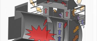
Now the principle of operation of a rocket furnace looks somewhat different. Firstly, at the end of the horizontal fire channel, afterburning of pyrolysis gases occurs due to the supply of secondary air. Secondly, combustion products that have a high temperature accumulate under the top of the bell (barrel), creating some excess pressure. As heat is transferred outward through the metal walls, these gases cool and flow downward.
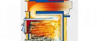
Since the cooling gases are supported from below by a new hot flow, they cannot descend in the same way, but pass through the space between the walls of the pipe and the barrel, safely exiting into the chimney channel. The flow of processes is well reflected in the diagram of a rocket furnace:
So, thanks to pyrolysis, the efficiency of wood combustion increases, and the use of free flow of gases creates a self-regulating system that limits the flow of fresh air into the firebox. The air mixture is supplied as the combustion products cool under the hood, making room for its new portion. Excessive pressure of hot gases “pushes” the cooled part out, so the operation of the stove depends little on the presence of draft in the chimney.
Types of rocket stoves
In this section we will look at the most common types of rocket stoves used in field and stationary conditions.
Simple metal stoves
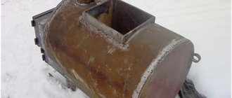
The simplest wood-burning jet stove is made from an L-shaped piece of large-diameter metal pipe. The horizontal part is short, it represents the firebox. The combustion chamber is located in the vertical part of the pipe, where wood actively burns. A small metal plate is often welded into the horizontal section, forming a blower. After warming up, the rocket furnace enters operating mode, and a flame bursts out of its vertical section (flame tube).
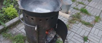
Such rocket stoves are used for cooking food in camping or outdoor conditions - due to their small area, they produce little heat, and the vast majority of the thermal energy is lost through the fire tube. Kettles, frying pans and pots are placed on this pipe so that the raging flame ensures their heating. To maintain traction, there are stands in the upper part of the pipe, on which the dishes are placed - combustion products can freely come out.
To make a metal rocket furnace made from an L-shaped piece of pipe more efficient, it is equipped with a metal casing made from an old barrel. A blower can be seen at the bottom of the barrel, and a fire tube peeks out from the top. If necessary, the internal volume is filled with insulation, for example, ash - it does not burn and retains heat well.
Metal rocket stoves with vertical fireboxes located at an angle to the flame tube are the most convenient. Often the combustion openings are closed with lids; in this case, air is taken through the ash pan. Sometimes the firebox is made larger in diameter than the flame tube to ensure long-lasting combustion.
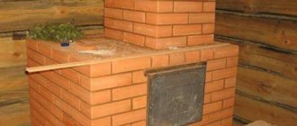
Simple brick ovens
A small-sized brick rocket stove is another simplest option for building a rocket stove with your own hands. Its assembly does not require cement mortar; it is enough to stack the bricks on top of each other to get a convenient brick outdoor unit for cooking at your disposal. In the section on self-assembly of rocket stoves, we will invite you to familiarize yourself with the simplest procedure for self-assembly.
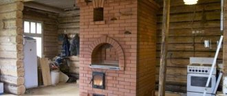
A rocket stove, made with your own hands from brick, can be used to heat households. In this case, a simple arrangement is not enough - you will have to build a stationary version using a special cement mortar. There are many procedures for this, you just have to choose the appropriate option. By the way, some versions of such furnaces include a water circuit.
Advantage of brick rocket kilns:
- Simple design;
- Long-term heat retention;
- The ability to create a comfortable warm bed.
Some models are made combined, using both steel and bricks.
Sophisticated rocket stoves
A jet stove for heating households or for a bath is characterized by increased complexity. The main link here is still the riser (fire tube), enclosed in a metal casing. Its upper part can be used for cooking, forming a kind of cooking surface. The firebox is made large to accommodate an increased amount of solid fuel. The starting materials are metal, bricks and clay.
Based on clay coating, streamlined rocket furnaces of irregular shape are made, which is well perceived by human vision.
There are projects for wood-burning rocket stoves that include additional modules. Their construction schemes include small boilers for preparing hot water, hobs, water jackets and even small ovens. Such stoves will help heat households and create comfortable living conditions for people.
A rocket boiler with a water jacket, created on the basis of a wood-burning stove, will help warm up a multi-room building. It is equipped with a water circuit for heating the coolant. Additional convenience is created by samples with beds - these beds are created on the basis of thermal channels between the flame and chimney pipes.
DIY jet stove assembly for heating
Construction of the furnace begins with preparatory work. First you need to decide on the place of construction. It is chosen based on the requirements that relate to solid fuel structures: wood or coal.
Once the location has been decided, it is necessary to properly prepare it for construction. The wooden floor under the stove is being dismantled. They dig a small pit and compact the bottom.
The barrel or cylinder also needs to be prepared for installation. To do this, cut off the lid and tap. Then the structure is cleaned. Next, prepare the solution.
Stages of construction of a jet stove with a stove bench:
- The bottom of the dug hole is lined with fireclay bricks. Formwork is made along the contour of the recess. Reinforcement is performed.
- Lay out the base and fill it with concrete. A day later, when the concrete has hardened, further work begins.
- The base of the stove is made of fireclay bricks. The side walls are raised and a lower channel is made.
- The combustion chamber is covered with brick. There are two holes left on the sides. One is intended for the firebox, the second is for the vertical pipe (riser).
- The metal body is equipped with a flange into which the horizontal channel of the stove will flow. All seams must be airtight and well sealed.
- A side outlet is attached to the horizontal pipe, which serves as an ash pan.
- A fire tube is made from brick. As a rule, it is square.
- The flame tube is equipped with a casing. The gaps are filled with perlite.
- The installation of the cap is done from a cut-off part of a barrel or cylinder. It is equipped with a handle.
- Equip the furnace body with brick or stone.
- Equip the front part of the stove. Lay out the required contour.
- A prepared barrel is placed on the base. The lower part must be sealed with clay.
- Using a corrugated pipe, a channel is formed connecting the firebox to the street.
- The heat exchanger pipes are connected to the lower pipe.
- Installing a chimney. All elements must be sealed using asbestos cord and fire-resistant coating.
Next, you should give the stove the shape of a stove bench. The external chimney is equipped with a fire and tar trap. When all the materials have dried, you can test the structure.
We make a stove - a rocket
The easiest way to make a light camp stove, shown in the drawing, is to find the following materials in the household:
- round steel pipe with a diameter of 133-150 mm and a length of 0.5 m;
- profile pipe 14 x 20 cm, length 0.4 m;
- sheet of metal 2-3 mm thick for grates;
- rod Ø8-10 mm for legs;
- scraps of iron for the stand.
A vertical round pipe is welded to the profile at an angle of 45°, then eyes for the legs are attached to the body (they should be easily removed). A grate is placed inside the inclined firebox, and a lid is attached to the outside. To make it easier to clean the ash below, it is advisable to install a second door.
Drawing of an improved version of the portable stove
The design of the furnace can be improved by organizing the supply of secondary air inside the flame tube. Modernization will increase the efficiency and duration of firewood burning. Drill holes on both sides on both sides, covering them with rocket “nozzles” according to the presented drawing. How this stove functions is demonstrated in the video:
From a gas cylinder
The following materials will be used to make a do-it-yourself rocket stove:
- round pipes with transverse dimensions of 70 and 150 mm; with a wall thickness of 4 mm;
- square corrugated pipe 150-200 mm in diameter;
- chimney pipe Ø10-15 cm;
- low-carbon steel (grade St20) sheet;
- dense basalt wool (80-120 kg/m3) or bulk fire-resistant materials, for example, vermiculite or perlite gravel.
To begin, cut the rolled metal into blanks in accordance with the drawing. Then you need to saw off the lid of the propane tank, after unscrewing the valve and filling the tank to the top with water. The tool is an ordinary grinder with a metal circle.
Further assembly technology is as follows:
- Cut the corrugated pipe lengthwise, 35 mm from the edge. One part will be used to make an ash pan, the second - a blower.
- Join the firebox and flame tube at an angle of 90°, making appropriate cutouts. Cut an opening on top of the combustion chamber where the loading hopper will be welded.
- Weld the riser with the firebox, then put on the casing from a 150 mm pipe, making a cutout at the bottom to fit the width of the combustion chamber.
- Install and scald the bunker for storing firewood. Secure the doors of the firebox and ash pan.
- Place perlite sand between the walls of the afterburner and the shell.
- Make a side opening in the cylinder to insert the finished structure. It is better to make the lid removable.
- Perform final assembly and weld the chimney pipe.
The master will tell you in detail about the manufacture of a rocket stove from a cylinder in the video:
Made of brick
The simplest rocket stove for cooking can be built from bricks without using mortar, as shown in the diagram with the order. Such a structure can be easily disassembled and moved if necessary.
The rocket stove with a stove bench must be placed on a foundation made of concrete or rubble stone. Material – ceramic or refractory brick, sand-clay or fireclay mortar, respectively. The finished base is covered with roofing felt for the purpose of waterproofing, then a continuous first row of bricks is laid. The further work order looks like this:
- Lay out the firebox, placing the bricks on edge. In the same way, cover the chamber, leaving an opening for loading firewood and a riser.
- Build an afterburner pipe from 9 rows of stones installed “on edge” with ligation.
- Place a pipe or tin buckets on the riser, fill the resulting cavity with insulation or regular sand.
- Place the barrel upside down, with the flue gas pipe coming out from the bottom.
- Build a brick bed from 3-4 horizontal channels.
- Coat the barrel and bench with clay mortar.
The length of the smoke channels inside the stove is limited by the draft in the rocket stove and the external chimney. It is better to keep the total length of the flue pipes within 4 m. To prevent the heater from smoking back into the room, raise the top of the chimney to a height of 5 m, counting from the grate. How to build a brick stove - a rocket without a barrel, watch the video:
Types of rocket stoves
Depending on the type of design, rocket furnaces are divided into:
- A rocket stove with a water circuit (if properly equipped, it can replace a full-fledged solid fuel boiler);
- Rocket stove from a gas cylinder;
- Rocket stove "Flint - Master";
- A simple brick rocket stove with a stove bench;
- Hiking options made from metal pipes.
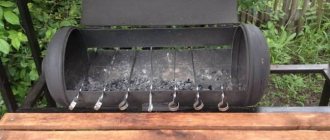
General view of a rocket stove made from a gas cylinder
How does a rocket stove work?
The device is the simplest - two principles of fuel combustion, borrowed from other stoves:
- Natural circulation of hot gases and smoke through the stove channels is a standard solution, as in a potbelly stove.
- Afterburning of unburned gases (pyrolysis) with limited access of oxygen to the combustion chamber.
The design of the simplest reactive stove, which is intended only for cooking, uses precisely the natural combustion of wood - in an open chamber it is impossible to create conditions for maintaining the pyrolysis reaction and the afterburning of unburned gases.
Let's consider a simple design of a direct combustion rocket stove, which is traditionally installed in an open area in the yard. You can quickly heat water on it or prepare lunch for your family on vacation. From the figure below it becomes clear that such a sample will require two sections of a cylindrical or rectangular iron pipe, which are connected to each other by welding at an angle of 90 0.
A horizontal section of a metal box acts as a combustion chamber; firewood is placed there. You can also organize fuel loading vertically - add a vertical iron cylinder on top of the horizontal pipe to load firewood. Thus, you will get a structure of three pipes or boxes, the lowest of which (horizontal) will work as a firebox. In a stationary scheme, the simplest stove design often uses red brick, which is placed on a clay mortar.
The efficiency of the design cannot be called satisfactory, so the craftsmen figured out how to increase its efficiency. The additional element is another pipe of larger diameter (as you can see, all materials are available and cheap), into which the main pipe of the riser stove (primary chimney) is installed. This increases the overall heating and the duration of heat retention.
On the diagram:
- Outer casing.
- A pipe that serves as a firebox.
- A channel for air outlet into the combustion chamber.
- Insulated area between the body and the riser. The same ash can serve as insulation.
Principle of operation
Despite the fact that a jet stove made from a gas cylinder is quite simple, its operation is based on advanced methods of generating heat by burning fuel:
- free circulation of heated air and gases. The firewood in its firebox burns due to natural draft generated by the influx of oxygen through the hole in the lower part of the structure (blower),
- afterburning of wood gases released during fuel combustion (pyrolysis). Part of the fuel, converted into a gaseous state, burns out in an additional heat exchange device and a horizontal section of the smoke exhaust channel located immediately behind the firebox. Wood gas moves slower in it than in a vertical channel, and a thick layer of heat-insulating material does not allow them to cool, which allows the process of decomposition and afterburning to take place more fully.
The vertical pipe in the rocket stove from the cylinder is installed above the firebox, according to the drawing, and is also insulated. The pyrolysis process when burning wood significantly increases the efficiency of the stove.
Principle of operation
Brick rocket stove with metal barrel
In the presented case, the work usually begins with preparing everything that may be needed during the construction of the furnace:
- heat-resistant red brick;
- metal barrel;
- metal chimney pipe;
- old metal barbecue;
- heat-resistant paint;
- metal fittings;
- a small amount of expanded clay, adobe and perlite;
- sand-cement mixture;
- metal brush;
- construction shovel and trowel.
Before you begin the actual construction of a rocket furnace with your own hands, you need to do the following preparatory work:
- In the floor, dig a hole as deep as a spade bayonet. This will allow you to hide the horizontal chimney under the floor.
- A metal barrel is used as a cap for the furnace device. First, the container is fired and cleaned, which is subsequently coated with heat-resistant paint.
It is important that the paint is applied after installing the flange to connect the main structure with the chimney. At the next stage, the foundation is constructed, for which manipulations are carried out in accordance with the dimensions indicated in the drawing in the following order
At the next stage, the foundation is constructed, for which manipulations are carried out in accordance with the dimensions indicated in the drawing in the following order.
- Prepare the formwork.
- At the place where the firebox is installed, several bricks are deepened into the soil.
- Reinforcement is placed at the bottom.
- Bricks are placed along the perimeter of the lower part of the firebox.
- The foundation is poured with a sand-cement mixture.
After the building mixture has completely dried, you can begin laying bricks. In this case, fire-resistant clay is used as a mortar.
- The first tier of masonry is erected, leaving only the opening for the firebox upward.
- On the 2nd row, the lower channel of the rocket furnace begins to be formed.
- On the 3rd row, the channel is overlapped so that there are 2 holes - for the firebox and the channel, located vertically.
- Before laying the vertical channel in a metal barrel, a flange is mounted to connect the chimney. It is also advisable to install a tee to clean the chimney pipe.
- The ascending part of the device is laid out using the “boot” method. Moreover, its internal cross-section should be 180 mm.
- You will also need an old water heater, which is placed on the rising part, and the resulting voids are filled with perlite.
- The base of the rocket stove is surrounded by bags filled with sand, and the base of the casing is covered with clay. The free space is filled with expanded clay.
- A chimney pipe is connected, and an inverted metal barrel is placed on the ascending part.
- After a test run of the rocket furnace, the barrel is painted using heat-resistant paint.
And finally, they line the chimney.
- The chimney pipe is lined with bags, which are first filled with sand and covered with expanded clay.
- The structure itself is formed using refractory clay.
I would like to note that during the operation of a rocket furnace, a lot of oxygen is required, so an air duct must be installed from the street. After this, an old barbecue is installed inside the firebox, which is closed with a lid. The seams are sealed with high quality clay. At this point, the construction of a brick rocket furnace with a metal barrel can be considered complete, and if anyone has any questions, you can watch the video.
Design options for rocket furnaces
If you need to assemble a rocket stove with your own hands, you should use the drawing of the portable Robinson model; it is constructed from scraps of a profile pipe and a metal stand on legs. All work involves welding. The schemes are quite variable, they allow the use of pipes of a different section, in this case all parameters must be adjusted to the proportions.
For the manufacture of large heating units, a 200 liter metal barrel or a gas cylinder is used. An outer cap is formed from these elements; fireclay bricks or medium-diameter pipes are used to assemble the internal parts. If you take a gas cylinder as a basis, you can end up with both a mobile structure and a full-fledged stationary device with a bench.
The most difficult step prior to assembly is calculating the thermal power of the device. Craftsmen recommend using ready-made drawings indicating the source materials; when choosing a diagram, you need to compare the potential dimensions of the furnace and the heated area.
To increase the efficiency of furnaces, modifications have been developed that can specifically collect heat:
- oven-stove,
- with water circuit,
- with a bed.
The first type is equipped with an extended cooking surface, on which several containers can be used simultaneously. A vertical pipe with a firebox and a door is located directly under the stove, under which there is also a horizontal channel. Hot air heats the hob both directly and through the duct. The outdoor model has stable legs that ensure the reliability and safety of the structure.
The furnace with a water circuit is mounted on a concrete base, which prevents distortions. The fire channel and the combustion chamber, lined with brick, form the lower part; an ash pan is also provided here (firewood is loaded vertically). The steel pipe in the form of a vertical channel is provided with thermal insulation and an outer casing. A heat exchanger with a water jacket is fixed on the latter.
The model with a couch is quite massive; the extension looks like a sofa or bed. If desired, you can lay a mattress here and use the platform as an additional sleeping place. The bed is laid out from stones combined with a clay mass, or bricks.
About the principle of operation of the rocket stove
- It is distinguished by direct combustion - flue gases move in the stove channels, being free and not driven by draft, as in the case of structures with chimneys
- Despite the fact that the dimensions of the furnace are small, pyrolysis afterburning of flue gases is organized. (pyrolysis is the process of decomposition of fuel into solid and gaseous phases with a deficiency of oxygen, in order to transfer the process from rapid oxidation to smoldering, slow. Smoldering occurs with complete combustion of both the generator gas CO and flue gas particles with a large release of heat)
In its simplest operating design, a rocket stove can be represented as follows: two pipes, one located horizontally, and the other directed towards the top. If it is possible to make welds, then one pipe is possible - bent by analogy.
The rocket stove has no “extra” parts - the fuel is placed directly into the pipe. During combustion, the hot flue gas, according to the laws of physics, will rush to the top, vertically. If you install a container on the top edge of the rocket tube, you can cook food and boil water very quickly. Of course, it is necessary to leave a path for the free exit of smoke from the rocket: for this, a gap is left between the container or stand and the pipe itself.
The simplest version of a rocket stove
A simple rocket-type camping stove is easy to make, saves time and resources during use, and is compact in size and dimensions. All work will require you to spend 2-3 hours with the preparation of tools and materials, which is very convenient when camping or in a summer cottage.
A design feature that needs to be taken into account is that the lower part of the unit, which acts as the bottom of the fuel chamber (grid), must be made movable. This is done to facilitate the process of laying firewood and loading it into the combustion bunker.
If wood chips are used, the retractable structural element serves as a convenient stand during the process of adding fuel to the stove. Additionally, the moving part greatly facilitates the process of cleaning the unit from ash.
A simple rocket stove made from a pipe
Preparation of materials
To make a rocket stove you will need to purchase:
- Pipe with a square cross-section (15 cm×15cm×3, 40.5 cm) – 1 pc.
- The pipe is also square in shape (it is optimal to choose 15 cm × 15 cm × 3, 30 cm) – 1 pc.
- Steel strip (recommended dimensions 30 cm × 5 cm × 3 mm) – you need to buy 4 pieces of such elements.
- Another option for steel strips (with parameters ideal for work: 14 cm × 5 cm × 3 mm) – 2 pcs.
- A grille, also made of good metal (steel) (choose dimensions 30cm×14cm) – 1 piece.
Additionally, you will need to buy a steel rod (3:5 mm) - 2.5 meters in order to make the grate yourself if desired. A high-quality Robinson oven with your own hands means minimal financial investment, a little attention and time.
Tools
To carry out all the necessary work you will need:
- Bulgarian.
- Welding.
- Metal scissors.
You should also have safety glasses and gloves.
Work is carried out according to the diagram and drawing indicated below:
Drawing of the simplest rocket furnace made from a profile pipe
Manufacturing instructions
All work on creating a heating device must be carried out in stages. The guide to action consists of several steps that must be followed sequentially:
- Square pipes must be cut into pieces of the size required according to the drawing.
- Make markings on them, taking into account that one of their edges will need to be cut (the cut angle is 45 degrees). The work is carried out using a grinder.
- The resulting pipes will need to be carefully welded - the result should be a structure shaped like a boot.
When making a Robinson oven with your own hands and using drawings, it is important to follow the recommendations for the size of the parts contained there. The next steps will be:
- Cuts are made (on top of the pipe or on its sides) - the dimensions are 20 mm deep and 3.5 mm wide (a stand for installing containers will be installed in them).
- Steel strip (which has parameters 30cm×5cm×3mm), 1 piece purchased, must be cut exactly in half.
- Mark the second remaining strip of steel (also with parameters 30cm×5cm×3mm) exactly in the middle.
- To ensure high-quality completion of all stages of work, weld elements on both sides of the cut strip to it (you should get a cross-shaped shape).
- Steel strips (dimensions to be chosen are 30cm × 5cm × 3 mm) - the remaining 2 pieces and the remaining 14 cm long sections are welded into a frame that will be retractable.
- The elements are welded not side by side, but overlapping.
Next, the following work is carried out, which are final.
On top of the finished frame, using a spot welding machine, a finished grille (purchased additionally/specially) or parts of a good steel rod cut to the required length are attached. The distance at which the parts are attached is 1 cm. Then, a stand is installed on top of the pipe, and the grate is pushed into the combustion hopper. The main work on the production of the furnace can be considered completed.
The stage of verification and test behavior begins. You need to put some solid fuel in the firebox and light the stove; if no problems are identified in its operation, you need to wait for all structural elements to cool completely. Finally, you can paint the stove to protect the parts from corrosion. For this, heat-resistant paint is used. You can increase the operating comfort by welding a handle to the combustion chamber door.
Making a rocket stove.
To make a stove you will need the following materials:
- Pipe length - 0.8 m (diameter 158 mm, wall thickness 4 mm).
- The pipe is 1.5 m long (diameter 127 mm, wall thickness 3.5 mm).
- Profile pipe 1 m long (section 120 x 120 mm, wall thickness 4 mm).
- Empty propane gas cylinder – 2 pcs.
- Sheet metal.
- Metal rods.
- Perlite.
- Chimney pipe with a diameter of 120 mm.
From the profile pipe we cut out two pieces 300 mm long and one piece for the sunbed 350 mm. Using a grinder, we cut out holes in the sunbed for the firebox and vertical pipe.
We cut one piece of profile pipe lengthwise and weld it to the firebox; this will be a channel for supplying air to the firebox.
We weld the firebox with the pipe.
We make grates from reinforcement rods, and doors are made for the firebox and ash pan.
Checking the performance of the furnace. The primary combustion chamber is ready, now let's make a secondary combustion chamber for pyrolysis gases.
An opening for the firebox is cut from the bottom of the cylinder, and a pipe bend with a diameter of 120 mm for the chimney is welded to the cylinder.
There is a door at the bottom of the chimney for cleaning the chimney.
A piece of larger diameter pipe is put on and welded onto the pipe, and the firebox is welded to the cylinder.
We fill the space between the pipes with perlite, which serves as a heat insulator, and weld it.
You need to cut off the bottom of the second cylinder and weld a hole from the valve; this will be a container for afterburning pyrolysis gases.
The parts of the cylinders are joined together in a groove made of two welded rings, so that the connection is more airtight; an asbestos cord is laid in the groove itself.
Useful tips for making a TT boiler
- If you want to make a TT boiler universal in terms of the use of raw materials, then use a pipe made of heat-resistant alloy steel for the combustion chamber.
You can significantly reduce the cost of building a unit if you take a seamless steel pipe of grade 20.
- Before installing the boiler in the place designated for this unit, carry out the first kindling outside, equipping the boiler with a temporary chimney. This way you will be convinced of the reliability of the design and will see whether the case has been assembled correctly.
- If you use a gas cylinder as the main chamber, then keep in mind that such a unit will provide you with combustion for 10-12 hours due to the small amount of fuel supplied. So, the small volume of the propane tank will decrease after cutting off the lid and ash pan. To increase the volume and ensure longer burning time, it is necessary to use two cylinders. Then the volume of the combustion chamber will definitely be enough to heat a large room, and there will be no need to add firewood every 4-5 hours.
- In order for the ash pan door to close tightly, preventing air from entering, it must be well sealed. To do this, lay an asbestos cord around the perimeter of the door.
If you make an additional door in the boiler, which allows you to “reload” fuel without removing the lid, it also needs to be tightly sealed using an asbestos cord.
For the operation of a TT boiler, the diagram of which we attach below, any solid fuel is suitable:
- hard and brown coal;
- anthracite;
- firewood;
- wood pellets;
- briquettes;
- sawdust;
- slates with peat.
There are no specific instructions on the quality of fuel - any will do. But keep in mind that with high fuel moisture, the boiler will not provide a high efficiency.
DIY jet stove assembly for heating
Construction of the furnace begins with preparatory work. First you need to decide on the place of construction. It is chosen based on the requirements that relate to solid fuel structures: wood or coal.
Once the location has been decided, it is necessary to properly prepare it for construction. The wooden floor under the stove is being dismantled. They dig a small pit and compact the bottom.
The barrel or cylinder also needs to be prepared for installation. To do this, cut off the lid and tap. Then the structure is cleaned. Next, prepare the solution.
Stages of construction of a jet stove with a stove bench:
- The bottom of the dug hole is lined with fireclay bricks. Formwork is made along the contour of the recess. Reinforcement is performed.
- Lay out the base and fill it with concrete. A day later, when the concrete has hardened, further work begins.
- The base of the stove is made of fireclay bricks. The side walls are raised and a lower channel is made.
- The combustion chamber is covered with brick. There are two holes left on the sides. One is intended for the firebox, the second is for the vertical pipe (riser).
- The metal body is equipped with a flange into which the horizontal channel of the stove will flow. All seams must be airtight and well sealed.
- A side outlet is attached to the horizontal pipe, which serves as an ash pan.
- A fire tube is made from brick. As a rule, it is square.
- The flame tube is equipped with a casing. The gaps are filled with perlite.
- The installation of the cap is done from a cut-off part of a barrel or cylinder. It is equipped with a handle.
- Equip the furnace body with brick or stone.
- Equip the front part of the stove. Lay out the required contour.
- A prepared barrel is placed on the base. The lower part must be sealed with clay.
- Using a corrugated pipe, a channel is formed connecting the firebox to the street.
- The heat exchanger pipes are connected to the lower pipe.
- Installing a chimney. All elements must be sealed using asbestos cord and fire-resistant coating.
To properly assemble a jet stove with your own hands, you should first watch a training video and study the recommendations of specialists
Do-it-yourself rocket stove - drawings and manufacturing process: do it according to instructions, video
A do-it-yourself rocket stove, the drawings of which most home craftsmen would probably like to have in their archives, can, in principle, be made even within one day, since its design is not at all complicated. If you have the skills to work with tools, read blueprints, and have the necessary materials, then making a simple stove of this type will not be difficult. It should be noted that it can be made from a variety of materials that are at hand, but much will depend on where the stove is planned to be installed. The rocket stove has a slightly different operating principle from other heating devices, and can be either stationary or portable.
DIY rocket stove drawings
Stationary rocket stoves are installed inside the house along the walls or on a designated area for cooking in the courtyard of the house. If the stove is installed indoors, it can heat a room up to 50 square meters. m.
Stationary rocket stove with heated bench
Portable versions of the rocket stove are usually very small in size and can easily fit in the trunk of a car. Therefore, when going out, for example, to a picnic or to the dacha, such a stove will help you boil water and cook lunch. Moreover, the fuel consumption in the rocket stove is quite small; even dry branches, splinters or tufts of grass can be used as fuel.
The principle of operation of a rocket-type stove
Despite the simplicity of the rocket stove design, its design uses two operating principles that the developers borrowed from other types of solid fuel stoves. So, for its effective operation, the following principles are taken:
- The principle of free circulation of gases released from fuel through the created stove channels, without the forced creation of chimney draft.
- The principle of afterburning pyrolysis gases released during fuel combustion in the mode of insufficient oxygen supply.
In the simplest designs of rocket stoves, which are used only for cooking, only the first principle of operation can operate, since in them it is quite difficult to create the necessary conditions for the flow of pyrolysis and the organization of afterburning of gases.
To understand the designs and understand how they work, you need to consider some of them one by one.
The simplest design of a rocket stove
To begin with, it is worth considering the simplest design of a direct combustion rocket stove. As a rule, such devices are used only for heating water or for cooking, and exclusively outdoors. As can be seen from the figure below, these are two sections of pipe connected by a bend at a right angle.
The simplest design of a rocket stove
The firebox for this furnace design is the horizontal part of the pipe, and fuel is placed in it. Often the firebox has a vertical loading - in this case, three elements are used to make the simplest stove - these are two pipes of different heights, installed vertically and connected from below by a common horizontal channel. The lower pipe will serve as a firebox. To make a stationary version of the simplest design, a brick is often used, installed on a heat-resistant mortar.
The simplest rocket stove made of brick
To achieve higher efficiency, the furnace was improved, and additional elements appeared, for example, the pipe began to be installed in a housing, which increases the heating of the structure.
Diagram of a simple rocket stove with an insulated riser
1 – outer metal body of the furnace.
2 – pipe – combustion chamber.
3 – a channel formed by a jumper under the fuel chamber and intended for the free passage of air into the combustion area.
4 – the space between the pipe (riser) and the body, densely filled with a heat-insulating composition, for example, ash.
The furnace is heated as follows. A light combustible material, such as paper, is first placed in the firebox, and when it flares up, wood chips or other main fuel are thrown into the fire. As a result of the intense combustion process, hot gases are formed, rising through the vertical channel of the pipe and escaping outside. A container for boiling water or cooking food is installed on the open section of the pipe.
An important condition for the intensity of fuel combustion is the creation of a gap between the pipe and the installed container. If its hole is completely blocked, then combustion inside the structure will stop, since there will be no draft that supplies air to the combustion area and lifts the heated gases upward. To avoid problems with this, a removable or stationary stand for the container is installed on the upper edge of the pipe.
Stand for placing dishes
This diagram shows a simple design with a door installed on the loading opening. And to create draft, a special channel is provided, which is formed by the lower wall of the combustion chamber and a plate welded at a distance of 7÷10 mm from it. Even if the firebox door is completely closed, the air supply will not stop. In this scheme, the second principle is already beginning to work - without active access of oxygen to burning wood, the process of pyrolysis can begin, and the continuous supply of “secondary” air will contribute to the afterburning of the released gases. But for a full-fledged process, one more important condition is still missing - high-quality thermal insulation of the secondary combustion chamber, since the combustion process of gases requires certain temperature conditions.
The principle of operation of the simplest rocket stove
1 – air channel in the combustion chamber, through which air is blown when the firebox door is closed;
2 - zone of the most active heat exchange;
3 – upward flow of hot gases.
Video: a version of the simplest rocket stove from an old cylinder
Improved rocket furnace design
The rocket stove is quite amenable to improvements.
The design, intended for both cooking food and heating the room, is equipped not only with a combustion door and a second body, which serves as a good external heat exchanger, but also with an upper cooking surface. Such a rocket stove can already be installed inside the house, and the chimney pipe from it is led outside. After such a modernization of the furnace, its efficiency increases significantly, since the device acquires many useful properties:
- Due to the second outer casing and insulating heat-resistant materials that thermally insulate the main pipe of the furnace (riser), hermetically sealing the upper part of the structure, the heated air maintains a high temperature for much longer.
More advanced rocket furnace design
- A channel for supplying secondary air was installed in the lower part of the body, successfully providing the necessary air supply, for which an open firebox was used in the simplest design.
- The flue pipe in a closed design is not located at the top, as in a simple rocket stove, but at the lower rear part of the body. Thanks to this, the heated air does not go directly into the chimney, but is able to circulate through the internal channels of the device, heating, first of all, the hob, and then diverging inside the housing, ensuring its heating. In turn, the outer casing gives off heat to the air around it.
Diagram of the design and operation of an improved rocket stove (with recommended dimensions)
This diagram clearly shows the entire process of operation of the stove: in the fuel bunker (item 1) preliminary combustion of fuel (item 2) occurs in the mode of insufficient air supply “A” - this is regulated by a damper (pos. 3). The resulting hot pyrolysis gases enter the end of the horizontal fire channel (item 5), where they are burned. This process takes place thanks to good thermal insulation and the continuous supply of “secondary” air “B” through a specially designed channel (item 4).
Next, the hot air rushes into the internal pipe of the structure, called the riser (item 7), rises along it to the “ceiling” of the body, which is the hob (item 10), providing its high-temperature heating. Then the gas flow passes through the space between the riser and the outer drum housing (item 6), heating the housing for further heat exchange with the air in the room. Then the gases go down and only after that they go into the chimney pipe (pos. 11).
In order to achieve maximum heat transfer from the fuel and provide the necessary conditions for complete combustion of pyrolysis gases, it is important to maintain the highest and most stable temperature in the riser channel (item 7). To do this, the riser pipe is enclosed in another pipe of a larger diameter - the shell (item 8 ), and the space between them is tightly packed with a heat-resistant mineral composition (item 9), which will serve as thermal insulation (a kind of lining). For these purposes, for example, a mixture of kiln masonry clay with fireclay sand (in a 1:1 ratio) can be used. Some craftsmen prefer to simply fill this space very tightly with sifted sand.
Find out what kind of wood is best to burn the stove with, and also check out tips on selection and storage from our new article.
Increasing the efficiency of heat extraction in rocket stoves
To increase the efficiency of the rocket stove, other designs with more efficient heat extraction were developed, both for using the device outdoors and for indoor use - for heating rooms or heating water.
Stove-oven
For cooking or preparing food for the winter, stoves are made that are designed according to the principle described above, but have an extended cooking surface that allows you to install several containers at once.
In this model of a rocket stove, a vertical pipe with a top-loading firebox built into it, which has a door, is located under the cooking surface. Therefore, hot air heats it directly, and in order for the entire panel to be hot, heated gases, collecting under the panel, are directed into a horizontal channel passing under its entire surface and connected to a vertical section of the chimney.
Rocket stove - stove
Additionally, the structure is equipped with legs, which makes it stable and reliable. It should be noted that when such a stove is not used for its intended purpose, it can be used as an ordinary garden table.
In addition to this outdoor model, several types of structures have been developed for indoor use to effectively heat rooms or heat water.
Rocket stove with water circuit
A rocket furnace with a water circuit consists of the following elements:
Diagram of a rocket stove with a water heating circuit
- The stove is installed on a solid concrete base to avoid distortions and deformation of structures.
- The lower part of the structure, which includes the combustion chamber (item 2) and the fire channel, is laid out of fireclay bricks (item 1). The firebox has a vertical loading. At the bottom there is an ash pan (item 3) with a side door for regular cleaning of the stove from accumulated ash.
The lower part of the furnace, lined with fireclay bricks
- The vertical channel (riser) (item 4) is made of a steel pipe, which is covered with a thick layer of thermal insulation (item 5) and an outer metal casing.
- A heat exchanger assembly with a water jacket in the walls (pos. 6) and horizontal plates that create a kind of labyrinth (pos. 7) to ensure maximum heat exchange area and time is hermetically fixed on top of the outer casing.
Attempts are being made to install a water register in this location. However, as practice shows, this approach is impractical - the temperatures here due to the afterburning of pyrolysis gases are very high, and the pipe register has every chance of quickly burning out.
- Hot air, passing through the heat exchanger, bending around the metal plates, heats the entire massive block, and the metal gives off heat to the water circulating through the water jacket.
- Next, the cooled gas flow goes into the chimney pipe (pos. 8).
- Water circulation occurs through a heat accumulator (item 9), which may well be made from an old boiler or other closed container with valves for connecting cold and drawing hot water. The option of connecting a heating radiator is not excluded, although, in truth, such a stove is unlikely to justify itself in such a role.
- Hot water from the heat storage tank through a pipe connected to it (item 10) can be directed to water intake points for domestic needs.
Such a rocket stove is perfect for installation in a country house or in a private house, where it is possible to connect such a heat storage tank to an autonomous water supply system. The stove will help to significantly reduce the cost of heating water and heating, since this model does not require a large amount of solid fuel or connecting it to any additional energy sources.
Rocket stove with bench
Another way to effectively use a rocket stove is to equip a fairly massive structure with a heated bench. It should be noted that such a bed can take the form of a bed or sofa, successfully replacing these pieces of furniture, since by laying a mattress on its surface, you can comfortably settle down for a day or night rest. The bed can be made of brickwork or stones and clay mass.
A stove like this with a stove bench will not only heat the room, but also decorate it.
The design of this version of the rocket stove consists of the following components and elements:
- A lid-closable firebox with vertical fuel loading with a secondary air intake chamber located in its lower part.
- The furnace goes into a horizontally located fire channel, at the end of which the pyrolysis gas is burned.
- The hot gas flow rises through a vertical channel (riser) to the hermetically sealed “ceiling” of the housing, where it transfers part of the thermal energy to the horizontal plate - the hob. Then, under the pressure of hotter gases following, it diverges into heat exchange channels, giving off heat to the surfaces of the drum, and falls down.
- At the bottom of the stove there is an entrance to horizontal pipe channels that run under the entire surface of the stove bench. Moreover, in this space one, two or more turns of corrugated pipe can be laid in the form of a coil, through which hot air circulates, heating the stove bench. This heat exchange pipeline is connected at the end to a chimney pipe led outside through the wall of the house.
General diagram of a rocket stove with a heated bench
- It should be noted that if the bench is made of brick, the channels can also be laid out of this material, without the use of metal corrugated pipes.
- The heated stove and bench, releasing heat into the room, will themselves serve as a kind of “battery”, capable of heating an area of up to 50 m².
The metal drum of the furnace can be made of a barrel, gas cylinder or other durable containers, and also made of brick. Usually the material is chosen by the craftsmen themselves according to their financial capabilities and ease of work.
A rocket stove with a brick bench looks neater and is somewhat easier to install than a clay version, but the cost of materials will be about the same.
Video: another original solution to increase the heating efficiency of a rocket furnace
We build a rocket stove with a stove bench out of brick
What is needed for the job?
The brick heating structure proposed for execution is designed on the principle of a rocket stove. The size of the structure with standard brick parameters (250 × 120 × 65 mm) will be 2540 × 1030 × 1620 mm.
Our task is to build such an original rocket stove with a warm bed out of brick
It should be noted that the design is divided into three parts:
- The oven itself – its size is 505×1620×580 mm;
- Firebox – 390×250×400 mm;
- Bed 1905×755×620 mm + 120 mm headrest.
To lay the stove you will need the following materials:
- Red brick – 435 pcs.;
- Blower door 140×140 mm – 1 pc.;
- Cleaning door 140×140 mm – 1 pc.;
- A fire door is desirable (250×120 mm - 1 piece), otherwise there is a risk of smoke in the room.
- Hob 505×580 mm – 1 pc.;
- Rear metal shelf panel 370×365 mm – 1 pc.;
- Asbestos sheet 2.5÷3 mm thick to create a gasket between metal elements and brick.
- Chimney pipe, 150 mm in diameter, with a 90˚ outlet.
- Clay and sand for mortar or a ready-made heat-resistant mixture. It should be noted here that for 100 bricks laid flat, with a joint width of 5 mm, 20 liters of mortar will be required.
The design of this rocket stove with vertical loading is quite simple, trouble-free and efficient in operation, but only if its masonry is done with high quality, in full accordance with the order.
If you have no experience as a mason or stove maker, but have a strong desire to install such a heating device yourself, you should play it safe and first lay the structure “dry”, without mortar. This process will help you figure out the location of the bricks in each row.
In addition, to ensure that the seams are the same width, it is recommended to prepare gauge wooden or plastic slats for masonry, which will be laid on the previous row before laying the next one. Once the solution has set, it will be easy to remove them.
Under the laying of such a stove it is necessary to have a flat and solid foundation. Despite the fact that the design is quite compact and its weight is not as great as, for example, a Russian stove, a floor laid with thin boards will not be suitable for its installation. In the case where the floor, although wooden, is very durable, before starting laying under the future stove, it is necessary to lay and secure a heat-resistant material, for example, asbestos 5 mm thick.
Order of a brick rocket stove with a stove bench:
| Illustration | Brief description of the operation performed |
| The first row is laid out solid, and the brick must lie in exact accordance with the pattern shown in the diagram - this will give strength to the entire base. For masonry you will need 62 red bricks. The diagram clearly shows the connection of all three sections of the furnace. The corners on the side bricks of the firebox facade are cut off or rounded - this way the structure will look neat. | |
| Second row. At this stage of the work, internal smoke exhaust channels are laid through which gases heated in the firebox will pass, giving off heat to the bricks of the stove bench. The channels connect to the combustion chamber, which also begins to form in this row. The first brick of the wall separating the two channels under the stove bench is cut diagonally - this “nook” will collect unburnt combustion products, and the cleaning door installed opposite the bevel will allow you to easily clean it. To lay a row you will need 44 bricks. | |
| On the second row, the doors of the blower and cleaning chambers are mounted, which are necessary for periodically tidying up the ash chamber and internal horizontal channels. The doors are secured with wire, which is twisted onto the ears of the cast iron elements and then inserted into the masonry seams. | |
| Third row. It almost completely repeats the configuration of the second row, but, of course, taking into account the laying in a bandage, and therefore it will also require 44 bricks. | |
| Fourth row. At this stage, the channels running inside the couch are blocked with a continuous layer of brick. A firebox opening is left, and a channel is formed that will heat the hob and discharge combustion products into the chimney pipe. In addition, a rotating horizontal channel is blocked from above, which removes heated air under the stove bench. To lay a row you need to prepare 59 bricks. | |
| Fifth row. The next stage is covering the bed with a second cross layer of brick. The smoke exhaust ducts and firebox also continue to be removed. 60 bricks are prepared for a row. | |
| Sixth row. The first row of the headrest of the couch is laid out, and the part of the stove on which the hob will be installed begins to rise. It still has smoke exhaust ducts. A row requires 17 bricks. | |
| Seventh row. The laying of the headrest is completed, for which bricks cut diagonally are used. The second row of the base under the hob rises. Laying will require 18 bricks. | |
| Eighth row. The furnace structure with three channels is being laid. You will need 14 bricks. | |
| The ninth and tenth rows are similar to the previous, eighth, they are laid out according to the same pattern, alternately, intertwined. 14 bricks are used for each row. | |
| 11th row. Continuation of masonry according to the scheme. This row will take 13 bricks. | |
| 12th row. At this stage, a hole is formed for installing the chimney pipe. The hole supplied under the stove is equipped with a brick cut obliquely for a smoother flow of heated air into the adjacent channel leading to the lower horizontal channels located in the stove bench. 11 bricks were used per row. | |
| 13th row. A base for the slab is formed, and the central and side channels are combined. It is through this that hot air will flow under the stove, and then flow into the vertical channel leading under the stove bench. 10 bricks are laid. | |
| 13th row. On the same row, the base for laying the hob is prepared. To do this, a heat-resistant material, asbestos, is laid around the perimeter of the space in which two vertical channels were combined. | |
| 13th row. Then, a solid metal plate is laid on the asbestos pad. In this case, it is not recommended to install a hob with opening burners, since when they open, smoke may enter the room. | |
| 14th row. The opening for the chimney pipe is closed and the wall is raised, separating the hob from the stove bench area. Only 5 bricks are used for a row. | |
| 15th row. This row raising the wall will also require 5 bricks. | |
| 15th row. On the same row, in continuation of the back wall, a metal shelf is fixed next to the hob, which can be used as a cutting board. It is attached to brackets. | |
| 15th row. The picture diagram shows well how a hob can be used. In this case, the pan is placed exactly on that section of the stove that will warm up first, since a hot air flow will pass under it. | |
| After completing all the work described in the order, a chimney pipe is built into the hole at the back of the stove, which is led out to the street. | |
| From the back, the design also looks quite neat, so it can be installed either near the wall or in the middle of the room. This stove is perfect for heating a country house. If the stove and chimney are decorated with finishing materials, then the structure can become an original addition, and a very functional one, for any private home. As you can see, the corner formed under the cutting shelf is very convenient for drying and storing firewood. | |
| To fully examine the structure, you need to see its projection from the end side. | |
| And the last picture clearly shows what should happen as a result of the work done, if you look at the stove from the side of the stove bench. |
In conclusion, I would like to especially note that the design of a rocket stove can be called one of the simplest and most accessible for self-production, compared to other heating devices. Therefore, if a similar goal has been set - to acquire a stove in the house, but there is clearly not enough experience in such work, then it is best to choose this option, since when building it, it is difficult to make a mistake in the configuration of its internal channels.
Iron cylinder stove
- Cylinder – gas, oxygen, carbon dioxide.
- Pipe ≥ 150 mm for fuel and loading chambers.
- Pipes 70 and 150 mm - for internal vertical chimney.
- Pipes 150 mm - for the outlet chimney.
- Insulation of any type, always non-flammable.
- Sheet metal blanks H = 3 mm.
The upper part of the cylinder is cut off by welding. For safety reasons, it is better to open the shut-off valve on it and fill it with water before cutting. On the sides you need to cut openings for the fuel chamber and chimney. The pipe under the firebox is connected to the vertical pipe of the chimney channel from the bottom of the cylinder.
After installing the internal elements, the cut top is welded back. The seams are checked visually and the main chimney is connected. If there is a water circuit, it is connected too. After this, the rocket stove can be tested.
