Where should a 3-way valve be installed and when is it not needed?
Before selecting a three-way valve, it is advisable to make sure that it is really necessary. After all, on the Internet and in real life there are enough advisers who poorly understand the essence of the issue. So, let's list the situations when this valve is really needed:
- To protect the solid fuel boiler from the supply of cold coolant and condensation on the internal walls of the firebox.
- To regulate the water temperature in heating circuits.
- To limit the heating of the coolant in underfloor heating circuits.
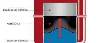
A lot has been said about condensate, which provokes the formation of sticky growths on the walls of the TT boiler chamber, including on our resource. It appears during the heating process, when the temperature in the firebox is already high, and cold water comes from the heating system. To avoid this, the supply and return lines are connected by a bypass, where a 3-way valve is installed. It forces the coolant from the boiler tank to flow in a small circle, and only when heated to 50-60 ° C does it begin to add water from the system.
A circuit with a bypass and mixer protects the TT boiler from condensation and temperature shock. System with several heating circuits operating in different modes.
Regulating the temperature in heating circuits using a mixing unit is necessary in the following cases:
- in complex heating systems, when several lines with different temperature conditions must be connected to a common comb, for example, a radiator network, heated floors and an indirect heating boiler;
- when connecting the same consumers to a buffer tank - a heat accumulator;
- when supplying heated water to the heat exchanger of a ventilation air handling unit used for air heating of a country cottage.
The valve in the heating circuit not only regulates the supply temperature, but also allows the boiler to heat the heat accumulator
Since a coolant with a temperature of no more than 50 °C is sent to the heating circuits of heated floors, and 85 °C can be supplied from the boiler, this should be limited. Usually (but not always!) the issue is resolved by installing a mixing unit with a 3-way valve on the distribution manifold. The latter mixes chilled water from the floor circuits with the “external” coolant coming from the boiler.
Scheme for preparing water at the required temperature for supply to underfloor heating loops
Now let’s identify situations where the purchase and installation of a mixer (or separator) is not necessary:
- If the length of each loop of a water heated floor does not exceed 50-60 m, which is quite possible to achieve, then regulation is done without a mixing unit. Instead, RTL type heads are installed on the return manifold, limiting the flow by the amount of coolant.
- When 2-3 heating units alternately operate to heat a private house, maintaining a constant network temperature of at least 40 °C, then there is no need to install a three-way valve for a solid fuel boiler.
- In heating systems with natural water circulation. The reason is the pressure drop across the valve, which prevents the movement of coolant. The same applies to heat accumulators operated according to a gravity flow scheme.
If you are interested in why it is better to choose RTL heads and how they control underfloor heating circuits, watch the video from an experienced master and our expert Vladimir Sukhorukov:
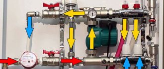
Description of the elements of the collector group
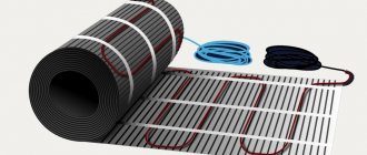
produces heating equipment for heating systems, radiator and floor. For water heating, a pipe and perforated insulation with fastening elements for the liquid line are purchased.
The pipes are connected to a comb, which consists of supply and return manifolds. What does a Valtec fluid distribution block provide?
- Supply manifold; a line with hot coolant is connected to it.
- The unit is equipped with flow meters that monitor the filling of the floor water circuit.
- An end tube with a float device is used to remove air.
- On the return circuit there are outputs for installing a thermal head. If the head is faulty, it is removed for repair. At the same time, the “warm floor” heating system operates in normal mode, without draining the coolant. The thermal head can be replaced with a servo drive or other control device.
- Flow meter valves; they are not permanently mounted on the hot water bar. A threaded connection is provided for them. If necessary, they can be removed.
- The system is equipped with a float device for air removal. A shut-off valve is connected to it, which allows you to remove the float if necessary.
- A drain valve is designed to remove coolant from the heating system. It has a hinged design.
- To ensure that the installation of the collector block for underfloor heating “Valtec” does not cause difficulties, the equipment kit includes adapter nipples and fittings. They are equipped with heat-resistant rubber gaskets.
- The operating temperature of the comb is 90 0C.
- Optimal pressure 8 bar.
- The filling level of the main line is 2.5 m3/h.
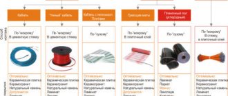
We recommend: What is film heated flooring?
Systems that do not include flow meters are cheaper, but if, along with large rooms, the mains of a bathroom or bathroom that are small in size are connected to the comb, then a device for filling the water circuit is necessary.
Along with a thermal head or servos, it regulates the filling of the water circuit and the room temperature. The flow meter is a valve. It closes, preventing hot water from entering a certain circuit. The device is triggered if the coolant flow exceeds the permissible limit.
The Valtek manifold for heated floors is made of stainless steel or nickel-plated brass. Fittings are made from hot-stamped brass. The air vent float is made of polypropylene.
- The size of the collector group depends on the number of outputs. If the block provides 3 outputs, then the length of the tube is 230 mm. With 7 outlets, the comb has a length of 430 mm.
- The pitch between the outlets is 60 mm.
- Outlet size 1”.
The comb is mounted on the wall using brackets. They have a figured design. The edge that fits tightly to the wall surface is provided for the cold circuit. A tube with hot coolant is fixed on the protruding surface.
Flow meters are located on the supply manifold. The equipment is configured when the circulation pump is turned on. Set the filling level of the highway to 2.5. The temperature parameters on the thermal head should be set before putting the heating system into operation.
Schemes for connecting the valve to the heating system
Once you have an understanding of what a three-way valve is and what its work is, you can consider various connection diagrams, depending on the purpose and role of the element in heating the house. Installation of a thermomixing 3-way valve is carried out in 4 cases:
- To protect a solid fuel boiler from the effects of condensation and temperature shock after sudden power outages.
- The coolant in the underfloor heating circuits should warm up to 45 °C, the temperature is maintained by a mixing unit with a three-way valve.
- To maintain the required water temperature in different branches of the system.
- When you need to connect an indirect heating boiler to a single-circuit gas boiler.
To protect a solid fuel heating unit from the formation of condensation, it is impossible to allow cooled water from the radiator network to be supplied to the boiler tank during its heating. To do this, use the following boiler connection diagram with a bypass and a three-way mixing valve:
The scheme works like this. Until the heat generator warms up, water circulates in a small circle through the bypass. When the coolant in the return heats up to 50-55 °C, the valve begins to open and mix in cold coolant from the system. When the heater reaches operating mode, the bypass is closed and the entire flow goes through the radiators. This topic is covered in more detail in the video:
In a heated floor system, this element performs the same functions. The circulation pump circulates the coolant through the heating circuits until it begins to cool. As soon as this happens, the sensor and thermal head will operate, after which the three-way valve will begin to add hot water coming from the boiler to the closed circuit. How to correctly install a heated floor manifold, pump and valve with your own hands is shown in the diagram:
The pump forces water to circulate along the contours of the heated floor, and the valve maintains its temperature at 35...45 degrees
The next example of the use and connection of this important part is the connection of a solid fuel heat generator and a buffer tank with a heat accumulator. To warm it up completely quickly enough, the temperature of the supplied coolant should be from 70 to 85 ° C, which is not at all necessary in a radiator heating system
A three-way valve installed behind the container along with a separate circulation pump helps to lower it.
In the scheme with a heat accumulator and a TT boiler, 2 mixing valves are used, each one regulates the temperature in its own circuit
A complex heating system of a large cottage can have many consumers connected via a hydraulic valve and a distribution manifold. Moreover, coolant with a different temperature must be supplied to each of the circuits. The highest is needed for an indirect heating boiler, so there are no control valves on the supply line to it. The remaining consumers need a colder coolant, and therefore they are connected through three-way valves.
There is a three-way valve in each circuit of the circuit, since it is necessary to prepare water at different temperatures. Only the DHW boiler is connected directly to the comb
In a scheme with an indirect heating boiler and a single-circuit gas boiler, you also cannot do without a 3-way valve. The element’s task is to switch the coolant flow to the DHW boiler coil at the command of the controller (the electric drive is activated).
While the coil is heating the boiler, the heating is inactive as the valve switches the flow between 2 lines
Technical characteristics of radiators
Competition in the radiator market is extremely high, so there are not many manufacturers producing and selling cast iron batteries on the domestic market.
Before purchasing, you should familiarize yourself with the technical characteristics of the most common cast iron heating radiators. This will allow you to choose exactly the products that are most suitable for the planned or existing heating system.
Manufacturers of cast iron batteries
If German batteries are particularly sophisticated, then the products produced by ChAZ are not inferior to them in their technical characteristics.
Moreover, the batteries of the Cheboksary Aggregate Plant are the best among Russian manufacturers . The main factories that offer cast iron batteries are:
- Adarad (Türkiye);
- Cheboksary Aggregate Plant (Russia);
- Viadrus (Czech Republic);
- Demrad (Türkiye);
- Minsk Heating Equipment Plant (Belarus);
- KIRAN (Ukraine);
- Konner (China).
There are many European manufacturers of cast iron radiators, but their products are not competitive. It has a high price, and the quality is comparable to domestic samples.
Devices for organizing heating in a vintage style are offered by a St. Petersburg manufacturer:
Overall dimensions of radiators
The sizes of radiators in the post-Soviet space were standardized. The distance between the center of the axes of the supply and discharge coolant pipes was 300 or 500 mm.
The depth of the sections and their width were not regulated and differed from one manufacturer to another. Most modern radiators are also adapted to these standards.
Cast iron radiators can be selected to any size required for placement under a window sill or in a wall niche
The most common model of cast iron batteries is MS-140. This is what stands in most Khrushchev and nine-story buildings built in the 60-80s of the last century.
The dimensions of its section are: center distance – 500 mm, total height – 588 mm, width – 93 mm, depth – 140 mm.
The wider the sections, the fewer of them are required to gain the required power, which means the number of potentially problematic joints is reduced.
The main goal of creating cast iron radiators with different dimensions is to enable the buyer to choose a model that best fits into the interior. Batteries with a total height of up to 400 mm, for example, fit perfectly into rooms with low window sills.
Appearance and structure of equipment
Almost all cast iron radiators are stacked. They are made of gray cast iron and consist of detachable sections that are connected using nipple bushings. This design allows you to form a solid battery of the required length and power. Paronite gaskets are placed between the sections.
Multi-column cast iron radiators are difficult to clean externally from dust, which significantly reduces the heat transfer of the batteries
In the horizontal plane between sections, water moves in only one direction. Vertically, the fluid flow occurs through one or more channels. With their number, the area of radiators and their power increases.
The disadvantage of multi-channel sections is their high cost and increased hydrodynamic resistance.
The classic "accordion" look of radiators is becoming a thing of the past. Due to the predominantly radiant method of heat transfer, manufacturers are seeking to increase the area of the battery façade, which results in a flatter appearance. An example is the Konner Modern500 model.
Radiators made of cast iron from the Konner Modern series, at a low cost, have a beautiful polished surface identical to aluminum panels
A number of imported models have decorative patterns on the surface, but the cost of such batteries is incomparably high.
The weight of cast iron sections is quite large. The need to maintain wall strength and maximum heating surface area does not allow engineers to greatly reduce the weight/power ratio. The weight of the section of the standard MS-140 model is 7.1 kg.
The unwinding of sections of cast iron radiators must be carried out gradually and synchronously from above and below, otherwise the threaded connection can be irreversibly damaged
The large mass of cast iron radiators also requires good fastenings. Batteries usually do not have special design elements for fixing to the wall. They are simply hung on special brackets, which are pushed into the spaces between the sections. There are also special feet for installing batteries on the floor.
Thermal power of devices
The power of radiator equipment is characterized by the ability to release thermal energy at the maximum operating temperature of the coolant. This indicator in cast iron radiators depends mainly on their surface area.
Depending on the model, the power can range from 80 to 200 W per section. These are passport values, which in real conditions can be much lower.
The recommended power of heating radiators is approximate. For regions with severe frosts, it may differ greatly from the standard
There is a classic formula for calculating the required power of a cast iron heating battery based on the volume of the room: for every 25-30 m3 radiators with a total capacity of 1 kW should be installed. If there are 2-3 external walls, this indicator should be adjusted towards increasing power. For more information on how to calculate the required number of batteries for heating, read this material.
To enhance heat transfer due to convection, some models of cast iron radiators are equipped with ribs between the columns. This design can increase the power of the section by 20-40%. You should remember the need to regularly clean such jumpers from dust.
Other equipment characteristics
When choosing radiators, you should pay attention to their other characteristics:
- maximum working pressure;
- coolant volume in the section;
- maximum coolant temperature.
All of the above indicators for cast iron batteries are higher than for aluminum and bimetallic counterparts. But the characteristics may differ for different models, which should be taken into account when selecting the components of a new heating system.
Models of the Minsk Heating Equipment Plant
Maximum settings are especially important when replacing batteries connected to a central heating system. When it is pressurized in the fall, excess pressure is supplied to the pipes, which can rupture unsuitable radiators.
This can result in flooding of both your own and the apartment located below, so special attention must be paid to the operating values of pressure and temperature of the coolant
Principle of operation
The operating principle of the heated floor mixing unit is as follows:
- The heated coolant moves along the heating circuit and reaches the distribution manifold;
- Next is a safety valve and a temperature sensor that measures the current state of the coolant;
- If the temperature of the hot water is excessive, then the damper opens, supplying the required volume of cold water to the system, due to which the coolant is mixed;
- When the coolant reaches a certain temperature, the supply of cold water stops.
A mixing unit with a manifold for a heated floor not only regulates the degree of heating of the coolant, but also allows it to circulate through the system - and the following elements are used to implement these functions:
- Safety valve. This element ensures the supply of the required amount of hot water. Its volume varies depending on the required temperature regime of the system.
- Circulation pump. A key element of the system that makes it possible for the coolant to move along each heating circuit, thereby ensuring uniform heat distribution in all areas of the heating system.
- Additional elements. Heating can be equipped with additional parts - bypass, air vents, valves and valves. The need for these elements is determined individually depending on the operating characteristics of the mixing unit.
The mixing unit is always installed in front of the entrance to the heating circuit of the heated floor, but there are no special requirements for the place of its installation itself - the mixer will be equally effective both in the immediate vicinity of the heated floor and when installed in a boiler room located at a distance from it.
What regulates the bypass of the TIM JH-1036 mixing unit.
The mixing unit has a conditional mixing chamber through which the underfloor heating circuit and the boiler heating circuit pass.
Typically, a heated floor mixing unit has one adjustment parameter - the water temperature in the heated floor circuit. The TIM JH-1036 mixing unit also has some kind of bypass, and even adjustable. And this is not the bypass balancing bypass, which is triggered by excessive pressure developed by the pump.
The pressure balancing bypass can be seen in the photo - the rightmost personal belongings.
I need it because it is possible to block all heating directions of the heated floor as a result of automatic regulation. By the way, I still haven’t figured out how to regulate the balancing bypass TIM M307-4 - maybe someone can tell me.
As for the mixing chamber bypass, you can find the following graphic explanation of the operation of the mixing unit bypass:
Little is clear from these diagrams.
Moreover, it is not clear what the numbers on the scale mean and what the current value is tied to. All this can be found out only by holding the TIM JH-1036 mixing unit in your hands:
It turns out that the adjusting screw turns the cylinder, which has a slot that closes when turned. Through this slot, water can be pumped by a circulation pump, bypassing the conditional mixing chamber.
It should be taken into account that the sticker with a scale from 0 to 5 can be pasted arbitrarily.
The maximum opening of the slot (pictured above) corresponds to setting the adjusting screw to position 5 (pictured below).
The technological ledge on the mixing chamber body can be taken as a conventional point for reading the scale value. When the scale value is 0, the gap is maximally closed. In this position, all the water pumped by the circulation pump along the contours of the heated floor passes through the mixing chamber.
With the bypass completely closed, the thermal power of energy taken by the mixing unit from the heating system is maximum.
If the bypass is completely open, then part of the water circulates through the heating circuits without entering the mixing chamber - and the thermal power of extraction is minimal.
But in practice it turned out that not only thermal power is regulated by the bypass.
Using drives
In addition to the thermostatic head, the valve can be controlled in other ways. The first of them is manual, when the depth of pressing of the rod is determined by turning the handle outside the body. Not the best option and is only suitable if the temperature of the water entering the pipes is constant. Another option is control using a servo and electric drive, receiving commands from the controller. To work together with different drives, another type of valve is used - rotary valves, whose device is shown in the figure:
This 3 outlet valve is very similar to a regular motorized ball valve
There is a certain similarity here with a ball valve, only the working rotary element has a different hole shape to allow coolant to flow in two directions at once. The operating principle here is simple: the axis rotates to the required angle, rotated by the drive. The latter is controlled by a controller that receives impulses from one or more sensors. Typically, valve actuators are installed in complex or automated heating systems with weather control.
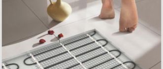
What is the purpose of the mixing unit?
Before installing a water heating structure for the floor, you should familiarize yourself with the sanitary requirements for the relative temperature of the floor. According to established standards, the floor temperature should not exceed more than 30 degrees; it is this optimal setting that guarantees convenience and comfort on the floor surface. Considering that the pipeline is located under the floor covering, the water in the pipes themselves should be about 5 - 10 degrees higher than in the room itself. But since the boiler of the central heating system heats the water for high-temperature radiators, its temperature is 90 - 95 degrees. This is where a mixing unit is used, which, when mixing two liquids of different temperatures, optimizes the average temperature of water for floor heating. Thanks to this, the floor remains comfortable and the concrete screed does not collapse.
So how does this device work in mixing water?
Why do you need a mixing unit?
It is worth immediately noting that the mixing unit for heated floors is used only in conjunction with a water heating system.
Typically the heating system is organized in this way:
- One heating boiler;
- Heating fluid;
- High temperature circuit for radiators;
- One or more circuits for heated floors.
The boiler heats the water to 75-95 degrees, and according to sanitary standards, the maximum surface temperature should not exceed 31 degrees. This is primarily due to the comfort of being barefoot, as well as the peculiarities of using many floor coverings for an apartment or house.
Advice! If we take into account the thickness of the screed and floor covering, then the temperature in the pipes should be 35-55 degrees. It is for this purpose that the underfloor heating circuits are connected not directly, but through a mixing unit. Their use is not necessary if the heat source does not heat the water too hot and the house no longer uses high-temperature circuits.
Valves for mixing units
Mixing units differ from each other depending on the use of certain types of valves. The most common valves are two-way and three-way.
Let us consider the features of both the first and second in more detail.
Two-way (feed) valve. This valve is equipped with a thermal head with a moisture sensor, which constantly checks it and, if necessary, cuts off the supply of hot water from the heating source.
As a result, already treated water enters the mixing unit, and if it has time to cool, it is automatically diluted with warmer water. Thanks to this, the warm floor does not overheat and can be used for quite a long time. The valve capacity is small, adjustment occurs slowly without noticeable changes.
Mostly for DIY installation, craftsmen choose just such a valve; it can be used to heat an area of maximum 200 square meters.
Three-way valve for mixing unit. This valve combines the characteristics of a bypass valve and a balancing bypass valve. It mixes hot coolant and cooled treated liquid inside itself. Sometimes such valves are equipped with servos that can control weather controllers and thermostatic devices.
Inside the valve there is a damper located between the water supply and return pipes. By adjusting its position, you can change the ratio of the amount of liquid supplied.
This valve is universal, perfect for large systems with numerous circuits and weather controllers.
But their use also has its disadvantages, in particular:
- upon a signal from the thermostat, the valves can open completely and let superheated water into the circuit, which will negatively affect the functioning of the heated floor to the point that it may simply burst under pressure;
- huge throughput, due to which the temperature can rise sharply even with a slight valve displacement.
Temperature sensors
Very often, heated floors are equipped with special outdoor sensors that automatically regulate their temperature depending on weather conditions. In particular, if it gets cold outside, the floor temperature begins to automatically increase.
It works like this: the valve rotates a maximum of 90 degrees. The controller divides them into 20 segments of 4.5 degrees each and checks the supplied temperature every 20 seconds. If the actual temperature does not correspond to the optimal temperature, the valve is turned 1 notch. Also, some sensors limit the water supply when no one is home.
Of course, this can be done manually, and tighten the valve each time, but it will be difficult to set the optimal heating mode.
Assembly of the mixing unit
When faced with such a seemingly difficult task, you first need to understand in detail the intricacies of this process. Below is an example of assembling a mixing unit with your own hands; the assembly will be made from metal components.
We will assemble it according to a scheme in which there is a thermostatic three-way mixing valve and a series connection of a circulation pump. To seal the seams, use flax tow and sealant paste; good reviews of Unipack paste.
You will need the following materials:
- Union nuts, American.
- Manual air vent.
- Nipples.
- Circulation pump.
- Thermometer.
- Check valve.
- Ball valve.
- Tees.
We are assembling on the basis of a three-way mixer of the ESBI thermostatic valve; the box indicates in which direction the water is mixed. The operating outlet temperature is 20-43 degrees Celsius, which meets the requirements for a heated floor system. This mixer already contains a thermostatic head, a temperature sensor and a temperature controller that allows you to set the temperature you need. On it itself, arrows indicate in which direction cold and hot water flows.
The next step is to purchase and install a circulation pump. It’s better not to skimp on it and buy a reliable one, since it will determine how evenly the heat will be distributed throughout the house and then the heating will be effective. After all, a pump that is economical in price means in 90% of cases its quick repair or replacement.
Wilo has proven itself well in this niche. Having picked it up, inspect it, determine in which direction it pumps liquid. Determine the direction of the drive axis; during installation, it should be located horizontally; this is one of the mandatory operating conditions for pumps that have a wet rotor installed in their design. Another prerequisite is that the switching box cannot be located under the pump.
If, nevertheless, it becomes this way for you, then rotate the upper element of the housing to which the box is connected 180 degrees. This can be done by using a hex wrench to unscrew the four screws that connect the two halves of the pump. Then carefully rotate the upper element relative to the lower pump element. Put everything back together and tighten the screws.
Photo of an example of a mixing unit for heated floors
The next thing we have to do is to install thermometers on the pipe where the supply takes place before the mixing process, then after the pump. Install the latest one at the outlet of the return manifold. Choose temperature sensors equipped with a probe that screws into central sockets. It would be advisable to verify each device.
Since in one chain they are subject to the same pressure, accordingly, their values should be the same. If possible, check with a reference device. If one of the devices has different readings, you can adjust this yourself. If you remove the cover, you will see a screw that you can use to adjust the readings.
So, the installation steps:
- Assemble the section from the primary supply to the mixing valve, connect the shut-off and ball valves and the tee under the temperature controller. Each of the four taps must be equipped with a union nut. This is done for ease of future maintenance.
- Connect the next outlet of the concentrate to the inlet pipe of the mixer with a three-way valve. Install a thermometer in the central socket of the tee.
- Install a bypass jumper, screw a coupling with an American connection to the second input. This is for ease of installation during maintenance.
- Then connect the tee to the jumper, with one side facing the system return and the other facing the manifold.
- The common return element includes one shut-off ball valve. There is no need to install a check valve as it will most likely not be useful.
- Then assemble a parallel section. Install the temperature sensor by first screwing in the tee.
- Then it was time to assemble the element between the pump and the supply manifold. It includes a coupling with an American connection, a triple connecting element for the temperature regulator, an extension cord, and a shut-off valve.
- Install a ball valve near the manifold.
- Screw the coupling onto the outlet of the mixing valve.
- Well, the almost final stage is the installation of the circulation pump. Insert the rubber O-ring and tighten the nut on the inlet pipe of the pump.
- Screw and crimp the union nut on the other side in the same way. So the mixing unit for the heated floor has been assembled.
This was the final step, then place this element where it will be installed.
Location of the collector unit in the underfloor heating system
Even before starting work on installing the underfloor heating manifold, care should be taken to install a metal protective cabinet, which may have an open or closed version. In some cases, the first option is chosen, since in this case access to it is simplified, although this negatively affects the service life of parts and connections that do not have reliable protection.
When deciding on space for a cabinet, it is necessary to take into account the placement of the contours of the water floor.
allocate space for the closet in the center
It is best if the equipment is installed in a niche, bounded on both sides by walls, where it is possible to carefully install the collector elements and supply the pipeline. Sometimes heated floors are installed in all rooms of the house. In this case, when installing a heating system in rooms with the largest area, it is necessary to install separate distribution units.
How to assemble a collector?
The Valtec distribution block is manufactured assembled. Flow meters are already installed on the hot tube. There are thermal heads on the cold line, but the product may only have outputs for attaching temperature control devices. They are protected by plastic caps. The manufacturer gives you the opportunity to choose which automation to install: thermal head, servo drive.
Some small elements need to be connected to the collector group:
- On the right, shut-off valves are connected to the tubes. There are 2 of them in the set.
- A float device is connected to the valves to remove air.
- Opposite the air vents, drain valves are connected to the underside of the tubes.
- The ends of the comb are closed with plugs.
We recommend: Should I use penoplex for heated floors?
A circulation pump and a three-way or two-way valve are separately connected to the comb. These devices must be purchased separately. They are connected on the left to the tube into which the cold coolant flows. Use brass threaded fittings.
The cold and hot circuits are removed from metal pipes that are connected to the boiler or furnace. They are connected via a bypass at the outlet of the collector group. A circulation pump with a temperature sensor is installed between the circuits.
The rotameter is adjusted when testing the heating system. The protective sleeve must be removed from the device. Using the red ring, the upper bushing, set the rotameter to zero.
Next, using the same bushing, install the valve on the o for large rooms, on the o for small rooms. To fix the rotameter parameters, turn the lower ring to the right until it stops.
Return the protective cap to its original place. The rotameter may not have a locking ring. In this case, the pipeline fill indicator is set without fixing. Valve operation must be checked regularly.
Valtek collectors for heated floors are installed with a liquid heating system. The coolant can be water, antifreeze, glycol fillers that do not freeze at low temperatures. If the heating system is not used, then the coolant does not need to be drained.
The number of circuits on the distribution block is 3-12 pcs. If necessary, additional equipment can be connected to them to increase the flow capacity of the coolant to all rooms in the house.
The comb is mounted on the wall or placed in a manifold cabinet. The manufacturer provides a 10-year warranty on the equipment. Service centers are located in St. Petersburg and Moscow. The block will last more than 50 years.
If necessary, the rotameter or thermal head can be replaced without turning off the heating system. When using a programmable thermostat, the operation of the heated floor control unit can be carried out through electronic gadgets.
We recommend: How does the underfloor heating calculator work?
YouTube responded with an error: The request cannot be completed because you have exceeded your quota.
- Related Posts
- How to choose a thermostatic valve for underfloor heating?
- What is a warm floor National Comfort?
- How is polystyrene foam used for heated floors?
- How is carbon heated flooring installed?
- How to connect a warm water floor in a house from a gas boiler?
- How to connect a mixing valve for a heated floor?
How it works
The three-way valve is installed in those sections of the pipelines where it is necessary to divide the flow of circulating fluid into 2 circuits:
- with variable hydraulic mode;
- with constant.
In most cases, a constant flow is required by those who are supplied with liquid of high quality and in designated volumes. It is regulated in accordance with quality indicators. As for the variable flow, it is used for objects where quality indicators are not the main ones. The quantity coefficient is of great importance there. Simply put, the coolant is supplied there according to the required quantity.
Note! Shut-off valves also include an analogue of the device described in the article - a two-way valve. How is it different? The fact is that the three-way option works on a completely different principle. The rod included in its design is unable to block the flow of liquid, which has constant hydraulic parameters
The rod included in its design is unable to block the flow of liquid, which has constant hydraulic parameters.
The rod is open all the time, it is adjusted to a particular volume of liquid. Consequently, users will be able to get the volume they need, both in terms of quantity and quality. In general, this device is unable to stop the flow of fluid to a network in which the hydraulic flow is constant. In this case, it may well block a flow of variable type, due to which, in fact, the possibility of adjusting the flow/pressure arises.
And if you connect a pair of two-way devices, you can get one, but three-way. But it is necessary that both work in reverse, in other words, when one valve closes, the next one must open.
conclusions
The operation of a water heated floor pump is comparable to the functions of the heart in living organisms - it promotes the movement of coolant within the system, allowing the operating temperature of the pipes to be maintained in a normal state without excessive cooling.
Maintaining constant pressure and flow stabilizes the functioning of the heated floor and helps overcome the hydraulic resistance of pipelines of complex configuration and small cross-section.
A correctly selected circulation mode makes the system operate efficiently, economically and extends the service life of all elements of the water heated floor. Date: September 25, 2021