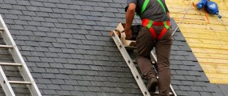
Despite the huge number of modern roofing materials that can very well imitate the natural appearance of tile coverings, many homeowners prefer ceramics. The fairly high cost of ceramic tiles does not allow the widespread use of this material in roofing devices. In addition, professional installation of ceramic roofing is classified as expensive.
[contents]
Construction of the lower roof.
• If the slope angle is less than 16 degrees or increased demands are placed on waterproofing due to the complexity of the roof or climatic conditions, then a lower roof must be installed under the tiles: a continuous deck of edged or tongue-and-groove boards and roll polymer-bitumen or polymer waterproofing.
• To make a waterproof bottom roof, fill a trapezoidal counter-lattice with a thickness of 40...50 mm over the decking, and only then fuse the waterproofing.
• When installing a lower roof, be sure to leave ventilation gaps at the ridge and ridge, similar to the film.
9. Laying the valley groove
• Bend the edges and profile the groove along the block. No special roofing tools are required for this operation.
• Start laying the gutter from the eaves (bottom to top). Place the groove on the flooring or thick sheathing and trim it along the contour of the inner square with a margin of 3...4 cm.
• The overhang aerial element or leveling bar must reach the visible valley line (13...15 cm from the axis of the groove) to securely support the first cut tile.
• Secure the groove to the substructure with six brackets using 2.8x25 mm galvanized roofing nails. You cannot nail the groove itself along its length with nails.
• Stepping back 1...2 cm from the top edge, nail the groove to the flooring with two nails to prevent it from sliding longitudinally.
• The minimum overlap of the next groove on the bottom is 10 cm; when laying, align the transverse ribs of the grooves.
The junction of the valleys below the ridge
• Lay the grooves with a gap of approx. 1 cm, secure them with nails and seal the joint with sealing tape of the appropriate color, profiling it along the edges of the groove.
Installation of joints at the same level for multi-gable roofs
• Lay and secure the grooves with nails. • Equip the ridge with aero elements or Figarol. • Seal the joint of cut ridge tiles with sealing tape or Wakaflex.
Bird and leaf protection
• The best protection against birds, dirt, snow and leaves getting under the tiles is provided by self-adhesive foam strips with water-repellent impregnation.
• If a foam strip is not used, then nail the eaves grille along the edge to the decking with galvanized nails.
The second way to lay the groove is on top of the thick sheathing
• This option is used when installing valleys of dormer windows or valleys over wide pipes, when the groove is released onto the tiles.
• In this case, nail the brackets to additional bars, otherwise the brackets will interfere with the even laying of the tiles. Bend the edge of the groove inside the valley. The foam strip can be trimmed to a height of 30...40 mm.
Release unit for the groove on the ramp
• Glue the outlet of the groove with Wakaflex and begin laying a groove 70...80 cm long with an overlap of the groove on the tile of at least 12 cm. • Use scissors to round the bottom edge of the groove and shape it to the shape of the tile using a hammer handle or a rubber mallet. • Construct valleys in the same way using grooves made of copper, zinc and galvanized steel.
Tile roof sheathing
Proper lathing is no less important than a strong rafter system. This is the basis on which all elements of the roofing system are attached: from roofing, vapor and waterproofing to eaves strips. If the sheathing is not strong enough or is designed incorrectly, sagging of the roof covering and damage to other roof elements may occur due to unevenly distributed load.
Rules for installing lathing for ceramic tiles
- For lathing, use square or rectangular bars with sides of 50 or 40 x 60 mm, respectively.
- 15-20 mm larger than standard bars reinforce the sheathing under the cornice.
- The width of the cornice board is 100 mm.
- The number of counter-lattice bars is determined by the number of rows of tiles + cornice.
- The sheathing beams are joined only on the rafters.
- The sheathing pitch is calculated based on the size of the tiles. To do this, use templates of the useful height of one tile and a coated cord fixed on the bars of the counter-lattice. On average, with a standard tile width of 400 mm, the lathing pitch is 310-345 mm.
- If the angle of inclination of the roof slopes is less than 16 degrees, continuous sheathing is required.
Installation of roof tiles
• Mark a trim line on the valley groove so that the overlap of the tiles on the groove is 8-10 cm. If the width of the groove from the center of the valley is 25 cm, the visible part, i.e.
not covered with tiles, it will be from 13 to 15 cm. • Mark the tiles along the drawn line. If the slope is flat, then you can tile the entire valley and mark the cutting line along a flat block. • Use half shingles to cut full shingles large enough to fit securely. The need for half tiles is approximately 1 piece. into two rows that fall into trimming. • To cut tiles, use a miter saw with a power of approximately 2 kW and a diamond blade for dry cutting of heavy concrete with a diameter of 230 mm. Be sure to use safety glasses and, if necessary, a respirator.
• The highest productivity and best accuracy are achieved when cutting tiles on a water-cooled machine.
Do not cut tiles directly on the valley, as this is unsafe for the roofer and may damage the gutter.
• After cutting, wash the tiles with water to remove dust and secure them to the sheathing with corrosion-resistant screws 4.5x50 mm, copper or zinc wire.
• On valleys, it is preferable to use wire fastening to prevent damage to the tiles from ice that may form on the valley.
• Glue the sealing foam strip along the edge of the groove. When laying tiles on it, use a knife to cut the pressed strip to close the side gaps between the tiles.
Calculation of the number of tiles
When determining the number of tiles, useful dimensions are used. How to determine the useful length is described above, and the useful width is indicated by the manufacturer. By multiplying them, you determine the usable area of one element. The total roof area is divided by the found value. Get the number of pieces. But a reserve is needed for fighting and pruning. Approximately 10-15%.
Even a simple gable roof will require a decent amount of money for material
Calculation example. We break tiles, the useful dimensions of which are 345 * 300 mm. The area of the gable roof of the bathhouse is 24 m2.
- We determine the usable area of the tiles: 0.345 x 0.3 = 0.1035 m2.
- We count the number of pieces for the entire roof. 24 / 0.1035 = 232 pcs.
- There will be 255 pcs in stock.
Now a little about the cost. The amount required is considerable: the price of one tile is from 1.6 € per piece (beaver tail) to 4.2 € / piece. It turns out that for this roof you will only need for ordinary tiles from 408 € to 1071 €.
The cost of side and ridge elements will also be added to the costs. Fasteners will also be needed. All this will require about 150-250 €. Not a cheap pleasure. But if you consider that the service life is calculated in decades, then it is not so expensive.
Sheathing device
• Calculate the pitch of the sheathing separately on the left and right gable, because
Cover lengths may not match. Mark the rows with a string, pulling it on the outer counter battens, and at the same time measure the difference in height of each counter batten. When further filling the sheathing, place slats or bars of the required thickness under it, leveling the plane of the slope. If the rafters are of high quality, then fill the sheathing using templates. • For lathing, use sawn softwood timber without wane and passing knots, meeting the requirements of SNiP II-25-80 “Wooden structures” with a maximum humidity of 25%.
Roof structure under tiles
Piece ceramic coating is suitable for roofs with a slope of 22 degrees, the optimal slope angle is 45 degrees. In exceptional cases, installation on flatter roofs (minimum 10 degrees) is allowed, with additional measures taken to ensure waterproofing and ventilation.
At the same time, the steeper the design, the better the ceramic coating will look. An angle of inclination greater than 60 degrees requires additional attention to be paid to securing the shingles.
The rafter system must be strong, made of beams of sufficient diameter to withstand not only the significant weight of the coating itself, reaching 80 kg per square meter. m, but also snow and wind loads, as well as the weight of additional elements such as insulation, roof windows, etc.
The basis for clay tiles is a flooring made of boards, consisting of two layers: sheathing and counter-lattice. If the attic is cold, then a layer of roofing material on top is sufficient; if you plan to install an attic, a superdiffusion roofing membrane or waterproofing film is laid.
Laying ordinary tiles.
• First, arrange the tiles in stacks of 5...6 pieces.
on all slopes for uniform load of rafters. Secure the first row with galvanized screws 5x50 mm and anti-wind clamps. Lay the tiles from bottom to top along the vertical layout marked on the sheathing. • As a rule, snow-retaining tiles with lattice or logs are installed in the second row. Install ventilation tiles, if necessary, along valleys, ridges, abutments and under the ridge.
• Attach the tiles on the slope with screws or anti-wind clamps in a checkerboard pattern, depending on the wind load and the angle of inclination.
• Moving on a tiled roof is easy and does not require special equipment.
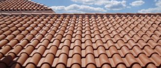
Natural tiles: pros and cons
The advantages include:
- The service life of ceramic roofing is the longest among all roofing materials and is more than 100 years. After this period, the material begins to gradually deteriorate under the influence of corrosion and other environmental factors.
- Aesthetic beauty. The vast majority of modern roofing materials, one way or another, imitate the appearance and texture of classical ceramics. Consequently, the visual parameters of a ceramic roof are the standard, and other materials try to imitate it.
- Manufacturability. This characteristic is due to the relative ease of installation of roofing made from this material. The use of such tiles does not require specialized expensive equipment.
- Possibility of installation at subzero temperatures , unlike most other roofing materials.
- Ceramics is a non-flammable material , therefore the ceramic coating belongs to the fire class NG and is completely fireproof.
- Ease of maintenance and repair. Ceramic roofing consists of individual tiles, each of which, if necessary, can be replaced without disassembling the roofing. Also, when dismantling the roof for repair work, such tiles can be reused.
- It has high noise insulation and heat insulation characteristics. It retains heat perfectly during winter frosts, and at the same time keeps the interior of the building cool in the summer heat.
- To produce such a coating, only natural ingredients , which allows us to call it an environmentally friendly material.
IMPORTANT!
Modern ceramic tiles are considered the most prestigious roofing material , due to which they are in stable demand in the private construction sector, despite all their shortcomings.
Natural tiles: photo of coating
The main disadvantages include:
- High price of material.
- The need to strengthen the rafter system due to the high weight of ceramic tiles.
- The material is laid only by hand , which creates some difficulties and slows down the roof installation process.
- Another disadvantage of ceramic roofing material is fragility . Ceramic tiles require careful handling during transportation and installation work.
Additional elements
Installation of a gable overhang.
• For sheathing pitches less than 33.5 cm, use side tiles with a cutout of 11 cm, and for larger pitches, with a cutout of 8.8 cm. Secure each tile with two galvanized screws 5x50 mm.
• The gap between the ends of the sheathing and the inner surface of the side tiles should be 1 cm.
• Another option for constructing gables is using lightweight side tiles made of painted aluminum. In this case, lay the row tiles on the gable overhang flush with an additional 50x50 mm bar.
• Place the side piece over the shingles and secure it to the gable beam with a roofing nail at the top and a screw and sealing washer near the bottom edge. The next element will cover the place of fastening with a nail.
Do not fasten the two lightweight side tiles with an overlap with a screw!
Stage VII. Fixing tiles using different methods
Now let's talk about fastening the tiles. Up to 60 degrees, most of the tiles do not need to be fastened at all; only the bottom row on the overhang, the top ridge rows and the side gable rows must be fixed.
They also fasten all the trimmed tiles, which are usually located on the valley, ridges and adjacent to the walls, roof windows and hatches. In regions with strong winds, shards are additionally secured with wire.
But groove tiles, which are also called castle tiles, are produced separately. It has the largest area and profiled shape, and this tile differs from others in the presence of locks.
The locks consist of two edges, top and side, which overlap the adjacent ones, snap into place and ensure reliable tightness of the coating. In addition, at the bottom, such tiles have protrusions that, during installation, cling to the sheathing bars.
The most popular models of such tiles are double S-shaped, Dutch and S-shaped Marseilles. Most of them have sliding locks, so the shingle periods can be made as wide or as narrow as possible. Thanks to the presence of such sliding locks, the tiles fit perfectly into the existing spacing of the bars, and there is no need to trim them:
In addition, basically all tiles today are produced with two manufactured holes for screws. They are not end-to-end, it is worth noting.
Therefore, if you decide to fasten the tiles, then these holes need to be drilled with a 6 mm drill and fixed at the top to the sheathing using two anti-corrosion screws 4.5 by 50 mm, and at the bottom with anti-wind clamps.
Also, if the slope has a length of more than 4.5 m, additional ventilation tiles must be installed on it. This is placed in the third row, in increments of 1 meter. If the slope is more than 7 m, then the ventilation tiles are laid in two rows:
Ventilation tiles are also needed where chimneys or roof windows are located, because these create obstacles to the air circulation under cover.
Installation of ridge and spine bars
Calculation of the height of the ridge bar/board
• Place the ridge tiles on the tops of the waves of row tiles cut along the ridge line (at least 2 pieces on each side).
• Measure the distance between the inside surface of the ridge tile and the top edge of the sloped rafter. Take measurements from the narrow part of the ridge tiles.
• Install the spine block or board so that the free gap between its top and the ridge tiles is 5 mm.
• 1 – slanted rafter leg • 2 – counter-batten • 3 – sheathing • 4 – figarole • 5 – fastening of ridge/ridge sheathing • 6 – spine beam • 7 – ridge tile • 8 – ridge clamp
Calculate the height of the ridge beam/board in the same way as the ridge
• Lay ridge shingles on two rows of shingles on each side of the ridge.
• Measure the distance between the inside surface of the ridge tiles and the point where the counter battens meet.
• Install the ridge block or board so that the free gap between its top and the ridge tile is also 5 mm.
Application of spinal ridge sheathing fasteners
• Bend the spinal bar fastening along the corner of the hip at the desired height.
• Install two fastenings at the beginning and end of the ridge, pull the lace along the edges of the fastening areas.
• Nail intermediate fastenings with galvanized nails 2.8x35 mm in increments of no more than 60 cm (4 nails for each fastening).
• Nail the core beam with a minimum cross-section of 50x50 mm to the fastening with galvanized roofing nails 2.8x25 mm.
On a skate
• Bend the fasteners to the desired height and install them under the top sheathing, so when nailing the sheathing, move the nail from the middle of the counter-lattice (rafter leg).
• Install intermediate fasteners with a cord at each joint of the rafter legs.
• When using concrete side tiles, cut the ridge block flush with the cutout in the side of the tile.
Tiling of ridges
• Cut the tiles with a gap of 2...3 cm to the center beam or board for ventilation of the roof and insulation.
• After drilling and cutting, be sure to wash the tiles with water to remove dust, as Figarol or Aeroroll ridge can only be glued onto clean tiles.
• Attach the cut tiles to the sheathing with corrosion-resistant 4.5x50 mm screws or to the core block with copper or zinc wire.
• It is most convenient to fasten the tiles with special stainless steel clamps.
Additional materials on the topic
Reviews about ceramic tiles
More details
Roofing units made of ceramic tiles
More details
Ceramic tiles koramic
More details
Your feedback, comments, questions
Dear visitors! We will periodically answer your questions in the comments as we are busy. In order for us to respond to you promptly (within an hour), you can: call, write a personal message or leave a request for a free consultation by phone.
Ventilation device for ridges and ridges. Installation of ridge tiles.
Ridge
• If the waterproofing film is laid with an overlap over the sloping rafter leg, then you can use the Aeroelement of the ridge for attics, Figarol or Aeroroll of the ridge. • When maintaining an additional ventilation gap between the film and the rafter leg, use only Figarol or Aeroroll ridge.
Horse
• Use the Coverland aerial element, the ridge aerial element for attics and Figarole.
• If installing ridge shingles over mortar, install vent shingles along the ridge and ridge. Consult with a specialist about the required quantity.
• Select ventilation elements depending on the length of the rafters, the shape of the roof and its complexity.
Laying Aeroroll or Figarol
• Use a dye cord to mark the center line on the spine block or board if they are uneven.
• Roll out the figarol along the marked line and secure with brackets or roofing nails 2.8x25 mm in increments of 30 cm.
• The overlap of the top roll on the bottom should be at least 5 cm. Remember that Figarol can only be glued to clean and dry tiles. It is preferable to work at an air temperature of at least +50 C.
• At lower temperatures, the surface of the tiles must be heated with a technical electric hair dryer. Do not use a gas burner or kerosene lamp.
• Remove the protective tapes from the adhesive rubber strips along the edges and glue Figarol only on the tops of the waves of row tiles.
• After this, glue Figarol over the entire surface of the tiles and roll with a special metal roller.
• The middle ventilated part of the Figarol must not be pressed against the backbone!
Conjugation of the hip ridge with the ridge
• In the upper part of the hip, place the Figarol with an overlap on another slope, and secure the aeroelements of the ridge or Figarol on top of it.
Laying of ridge aeroelements
• Attach the aeroelements to the ridge beam with galvanized nails 2.8x35 mm with a pitch of approximately 30 cm.
• The overlap of the elements is determined by the existing side cutouts.
• Start installation of ridge tiles on the leeward side to reduce the possible blowing of precipitation through the joints of the tiles. Arranging the beginning of the ridge with tiles and an end ridge element • Secure the ridge clamp with two roofing nails or screws, having previously tried on the ridge tiles and the end element.
• Place the ridge tiles in the clamp and secure them to the next clamp using a 5x70 mm galvanized screw.
• Using the longitudinal hole in the clamp, lay the tiles with a gap of approximately 1 cm.
• Secure the end ridge element to the spine beam with galvanized screws or nails.
Application of initial spine tiles
• Install the initial spine tile with a small protrusion and secure it with two galvanized screws 5x70 mm and 5x100 mm through the holes.
• Align the clamps along the center line marked on the Figarol. Secure the tiles with 5x70 mm screws.
Application of hip tiles
• Cut the last ridge tiles to the required length and trim their edges along the seam lines.
• Apply hip shingles and mark their outline on the ridge tiles.
• Cut the ridge tiles 6cm above the marked outline and drill 6mm holes for the screws.
• Install and secure the clamps.
• Secure the hip tiles with three ridge clamps and a 5x100mm screw.
Hip top structure without bell-shaped tiles
• At the top point of the hip, cut the ridge tiles tightly, drill 6 mm holes and secure with galvanized screws 5x70 mm.
• Seal the joints of the ridge tiles with sealing tape for valley joints or wakaflex of the appropriate color and roll them with a roller.
Important! At the junction it is allowed to install ridge tiles with a length of at least 23 cm.
Insulation and waterproofing
- The vapor barrier layer is attached to the rafters from the inside (from the ceiling) with vertical and horizontal overlaps of at least twenty centimeters.
- Fixed with wooden slats. In the future, when arranging the ceiling, the panels (boards) should not come into contact with the vapor barrier.
- The insulation is cut into blanks according to the width of the step between the rafters and placed between the rafters in a spacer.
Installation options for the top waterproofing layer
- Installation of the film directly onto the insulation is carried out with the steam-removing side facing outwards, i.e. towards the roof covering.
- The film should be rolled out along the cornice along the rafters, starting from the bottom row.
- The recommended overlap when installing the next row is approximately 10 cm for steep roofs. If the slope is less than 22 degrees, it is increased to 20 cm or the joints are taped with double-sided tape.
note
The film is secured with a stapler or roofing nails and finally fixed with counter-lattice boards.
Other methods:
- When using polyethylene-based membranes, the film is pulled over the rafters with a sag of one or two centimeters. At the same time, at least two centimeters should remain from it to the insulation. In cold weather, the film is stretched without sagging.
- With a small roof slope (within 16 centimeters), a welded roof can be used as a waterproofing layer. To do this, it is necessary to make a continuous flooring and fill it with trapezoidal counter-lattice slats up to 5 centimeters thick.
Installation of connections to pipes and walls using self-adhesive tape BRAAS Vakaflex.
Technical characteristics
Material: polyisobutylene mastic (PIB) with a reinforced aluminum mesh, adhesive tapes made of synthetic rubber 2 cm wide are applied on the reverse side along the edges of the roll. Size: length 5 m, width 28 cm. Temperature resistance: - 40...+100 C to DIN 52 133. Colors: red, brown, black, green. Weight: 5 meter roll approx. 5 kg. UV stability: complies with DIN 16 726.
Tool for working with Wakaflex • Roller • Folding meter • Pencil • Scissors
• Operating procedure
1. Arrange the bottom of the pipe. 2. Make side connections. 3. Glue the top of the pipe. 4. Install a Waka strip with heat-resistant dowels around the perimeter of the Wakaflex. 5. Apply sealing compound K.
• Lay the tiles around the pipe with a gap of 2...3 cm. If necessary, cut the tiles under the pipe to continue the row line and secure them to the leveling bar with 5x50 mm screws.
• IMPORTANT! Tiles and wall surfaces must be clean and dry. If you work at air temperatures less than +5 degrees. C, then use a technical electric hair dryer to warm them up.
Bottom of pipe
• Cut off the bottom strip of Wakaflex (length of strip = pipe width + 5 cm extra on each side of pipe).
• Fold the Wakaflex strip into a corner.
• Remove the middle protective film.
• Remove the protective film from the adhesive strip and glue the top part of the Wakaflex.
• Roll the adhesive strip to the pipe and the entire surface with a metal roller.
• Remove the film from the bottom edge of the Wakaflex and glue the roll only along the top of the waves of tiles.
• Glue Wakaflex onto the entire surface of the tiles using a roller.
• Cut the upper non-adhesive part of the Wakaflex at an angle of approx. 450, without cutting 1 cm to the point of intersection of the slope and the pipe line.
• Glue the cut sections onto the pipe and tiles.
Pipe side
• The side roll of Wakaflex should start from the bottom edge of the already glued strip and end 10...15 cm above the top of the pipe.
• Glue the side roll of Wakaflex to the pipe and tiles, roll it up with a roller.
• Stepping back 2...3 cm from the pipe line, make a cut to the point of intersection of the slope and the pipe. Do not extend the cutting line approximately 1 cm to this point.
• Cut the side parallel to the water drainage line. This piece will be useful to you later.
• Use scissors to round the bottom edges of the side strips to reduce the effect of wind.
• Glue the bottom of the roll and roll it with a Waka roller.
• Cut the top of the side roll towards the point where the line of the pipe and the slope intersect. Do not extend the cutting line to approx. 1 cm to this point.
• Glue the cut pieces onto the pipe and tiles and roll them with a Waka roller.
• Glue the left and right corners of the pipe in the upper part (remaining from the side strips) with pieces of Wakaflex to protect against sliding snow and ice.
• The overlap of the bandage strips on the side of the pipe should be approx. 2 cm.
Top of the pipe
To protect the roof from melt water, make the top roll of Wakaflex double.
• Cut two strips to the required length.
• Remove the protective film from the top strip and apply it to the bottom strip with an overlap of 5 cm. Roll the joint with a Waka roller.
• Place the double roll in the groove with a slight slope in any direction and glue Wakaflex to the pipe.
• Remove the protective film from the top strip and glue Wakaflex to the waves of the tiles.
• Glue and roll Wakaflex over the entire surface of the tiles, with the exception of the lower area (adjacent to the pipe and not covered by tiles) to drain rainwater and dirt.
• Make a cut down parallel to the pipe line, stepping back 2...3 cm from it. Do not bring the cutting line approximately 1 cm to the slope line.
• Cut off the bottom of the roll and use scissors to round the bottom edge.
• Glue the cut pieces onto the pipe and tiles and roll them with a Waka roller.
• If a snow bag may form above the pipe, then to protect the roof from the penetration of melt water during a thaw, bend the upper edge of the Vakaflex in the form of a bumper by 2...3 cm.
• Lay the tiles on Wakaflex.
Working with the Waka bar
Bottom of pipe
• Cut the bottom strip to the required length: The length of the strip is equal to the width of the pipe + 5 cm outlet in both directions.
• Cut the upper part 1 and bend it along the line of the pipe.
• Cut the lower part 2 and bend it along a line 1 cm away from the corner of the pipe.
• Bend the upper flange of part 1 with a hammer to the pipe.
• On the bottom 2, cut a corner parallel to the slope line.
• On the top part 1, mark and drill holes for dowels d 6mm
• Mark along the strip and drill 6x40 mm holes in the pipe.
• Secure the strip to the chimney with heat-resistant dowels and screws.
The fastening step is no more than 20 cm!
Pipe side
• Place the side strip parallel to the slope line and mark on it the outline of the bottom strip and the pipe line at the top.
Top edge of the side bar
• Cut part 1 along the pipe line.
• Cut part 2 along a line 1 cm away from the corner of the pipe.
• Secure the side strip with screws.
The fastening step is no more than 20 cm!
Top of the pipe
• Cut the top strip: Length of the strip = pipe width + 2 cm outlet on both sides.
• Mark the outline of the installed side strips on the top strip.
• Mark the upper part 1 and bend it along the pipe line. To do this, make sequential cuts u and v.
• Bend the lower part 2 along a line 1 cm away from the pipe. To do this, make cuts x and y.
• Cut off the raised edges w and z at the rake angle.
• Mark along the strip and drill 6x40 mm holes in the pipe for dowels.
• Attach the top strip to the pipe.
• Using a construction syringe, apply Sealant K into the flange of the plank along the entire perimeter of the junction.
Appearance of the finished junction
• The upper edge of the Wakaflex is protected from precipitation by a Waka strip, secured to the chimney with heat-resistant dowels and corrosion-resistant screws.
• Sealant K is applied to the flange of the strip - a one-component synthetic rubber that does not contain silicone.
Preparing the base
Scheme of a roof made of natural tiles
After strengthening the rafter system and immediately before laying ceramic tiles, you will have to perform a number of standard operations related to the arrangement of the so-called “roofing pie”.
The list of these measures traditionally includes the following standard operations:
- preparing waterproofing to protect the entire structure from moisture and avoid fungal infection of the wood;
- arrangement of a thermal insulation coating that additionally protects the roof from heat leaks through “cold bridges”;
- covering a layer of vapor barrier, thanks to which the roof will be reliably protected from condensation.
Waterproofing protection is required at roof slope angles up to 22 degrees. When calculating the material requirements (taking into account all the necessary allowances), the total area of the slopes should simply be multiplied by 1.4.
To fix the waterproofing layer on the rafter beams, you can use a special stapler used for fastening rolled materials. In this case, the amount of overlap of each subsequent layer on the previous one should be at least 10–15 cm.
To avoid heat loss through the roof structure, it will be necessary to lay a layer of insulation under the waterproofing, which can be mineral wool or polystyrene foam plates. When forming this layer of “roofing cake”, it will be necessary to provide ventilation gaps created artificially. Such gaps can be formed in the spaces between thermal insulation and waterproofing (by building up the sheathing elements) or by installing the so-called counter-lattice.
When preparing the sheathing itself, you should always remember that it is on it that the tile blanks will be laid in the future, so the distance between the individual beams should be selected taking into account the size of the tile sheet.
When arranging the roof, one should not lose sight of the issue of its vapor barrier, since the presence of condensation in the area of the insulation significantly reduces the effectiveness of thermal protection. To reliably protect the thermal insulation layer from destruction by condensate, an overlap of the vapor barrier film within 10 – 15 cm will be sufficient.
Installation of safety and snow retention elements.
• BRAAS safety system elements are designed for roofs with pitch angles from 150 to 520. They comply with the requirements of DIN 18160-5.
Material: hot-painted aluminum, galvanized steel.
Aluminum elements:
• Support / snow retention tiles - 420 x 180 mm; • Grate – 880 x 250 mm; • Safe step - 410 x 250 mm; • Yoke for fastening the footrest and grille; • Support for fastening round timber (logs up to 130 mm); • Support for fastening the snow-retaining grid;
Galvanized steel elements:
• Snow-retaining grid – 200 x 2500 mm; • Connecting clamp for snow guard.
Installation norm
• When the slope angle is no more than 450, it is allowed to install supporting elements through two rows. • At angles greater than 450, it is necessary to install support elements on each row.
Location of support tiles
• For an 88 cm grate - two support tiles through one row and half tile. The pitch along the axes is 60 cm. • For a 42 cm footboard - two support tiles through one half tile. The axial step is 30 cm.
IMPORTANT!
Be sure to install an additional support block under the supporting tiles.
• The thickness of this block should be 2 cm greater than the thickness of the sheathing; the tiles will rest on the supporting block with protrusions located on its back surface.
• Fix the support block at a distance of 230 mm from the top of the sheathing.
• Secure the supporting tiles with two galvanized screws 4.5 x 50 mm.
• Install the yokes onto the support shingles.
• Aluminum safety grilles (880 mm) can be installed next to each other in various combinations on the support tiles. In this case, the maximum gap should not exceed 5 cm; it is recommended to center the gratings.
• In this way, you can use ladders of various lengths (parallel to the ridge line) for convenient and safe operation of stove and fireplace pipes, ventilation shafts, roof ditches, etc.
Snow retention installation
• As a rule, snow-retaining gratings or logs are installed in the second row from the eaves overhang. The maximum pitch of snow-retaining tiles is 90 cm (every 2.5 row tiles).
• If there are increased requirements for reliability, install support bars under the tiles.
• Secure the shingles with the two ribbed galvanized nails included in the kit.
• Place attachments under a grate or log. Grate size: 200x2500 mm, log diameter no more than 130 mm.
• To join the gratings, use connecting clamps (requirement: 2 pcs./joint).
Rafter system for tile roofing
The length and cross-section of the rafter legs for a tiled roof depends on several factors. The wood for rafters must be well dried. It is better not to use boards with a moisture content of more than 15%.
In standard cases, timber with a section of 50 x 150 mm is used for rafters under ceramic tiles, and for reinforced rafters - 75 x 150 mm or 60 x 180 mm.
The pitch of the rafters depends on the angle of inclination of the roof slope and ranges from 0.8 to 1.3 m. When calculating the pitch width, the rule applies: the greater the height of the roof (which means the steeper the slope of the slopes), the wider the pitch of the rafter legs. For clarity, let’s give an example: for a roof with a slope angle of 15 degrees, the rafter pitch width is 80 cm, 75 degrees - 1.3 m.
There is also a direct relationship between the step width of the rafter legs and their length. Rule: the longer the rafters, the narrower the step. Long rafters experience increased deflection loads. To reduce them, a supporting system is constructed from supporting posts and struts.